 |
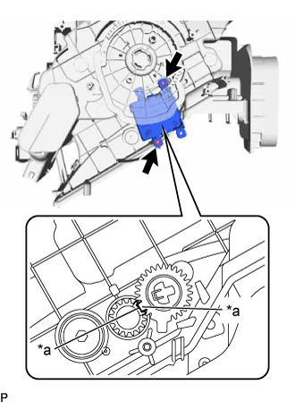
Using the reference point, install the No. 1 air conditioning radiator damper servo sub-assembly with the 2 screws.
| *a | Reference Point |
AIR CONDITIONING UNIT > REASSEMBLY |
| 1. INSTALL NO. 1 AIR CONDITIONING RADIATOR DAMPER SERVO SUB-ASSEMBLY |
|
Using the reference point, install the No. 1 air conditioning radiator damper servo sub-assembly with the 2 screws.
| *a | Reference Point |
| 2. INSTALL NO. 2 AIR CONDITIONING RADIATOR DAMPER SERVO SUB-ASSEMBLY |
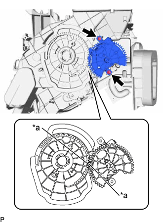 |
Using the reference point, install the No. 2 air conditioning radiator damper servo sub-assembly with the 2 screws.
| *a | Reference Point |
Install the No. 2 air conditioning radiator damper servo sub-assembly with the 2 screws.
| 3. INSTALL DRAIN COOLER HOSE |
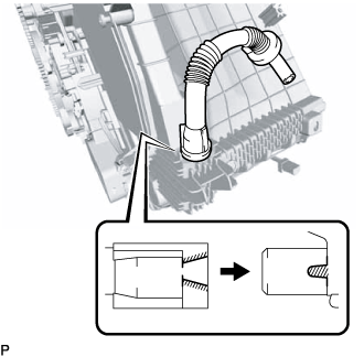 |
Align the drain cooler hose fitting and the protrusion of the lower heater case as shown in the illustration to connect the drain cooler hose to the heater case.
| 4. INSTALL FRONT EVAPORATOR TEMPERATURE SENSOR (NO. 1 COOLER THERMISTOR) |
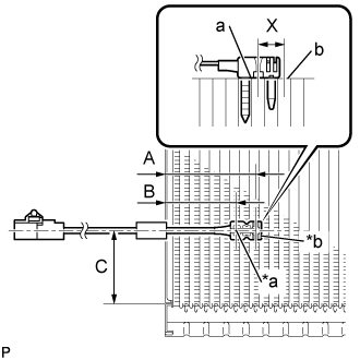 |
Install the No. 1 cooler thermistor as shown in the illustration.
| Mark | Measurement |
| A | 61.1 mm (2.41 in.) |
| B | 47.7 mm (1.88 in.) |
| C | 50 mm (1.97 in.) |
| *a | Secured Part |
| *b | Sensor Part |
| 5. INSTALL NO. 1 COOLER EVAPORATOR SUB-ASSEMBLY |
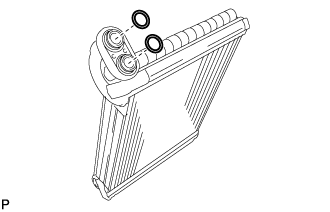 |
Sufficiently apply compressor oil to 2 new O-rings and the fitting surface of the No. 1 cooler evaporator sub-assembly.
Install the 2 O-rings to the No. 1 cooler evaporator sub-assembly.
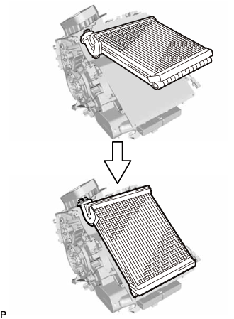 |
Install the No. 1 cooler evaporator sub-assembly with the No. 1 cooler thermistor to the upper heater case as shown in the illustration.
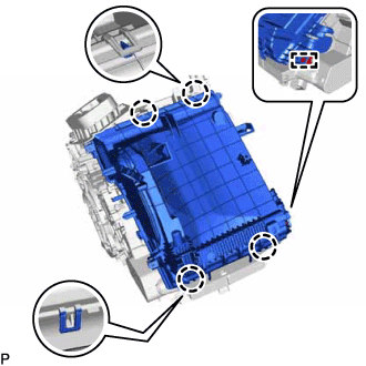 |
Engage the 4 claws and install the lower heater case.
Engage the clamp and connect the connector to the lower heater case.
for Type A:
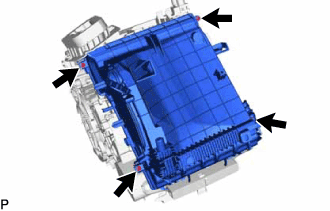 |
Install the 4 screws.
for Type B:
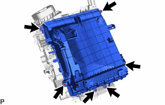 |
Install the 6 screws.
| 6. INSTALL COOLER EXPANSION VALVE |
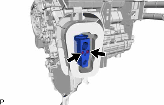 |
Using a 4 mm hexagon wrench, install the cooler expansion valve with the 2 hexagon bolts.
| 7. INSTALL HEATER RADIATOR UNIT SUB-ASSEMBLY |
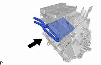 |
Install the heater radiator unit sub-assembly to the air conditioner radiator assembly.
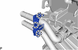 |
Engage the 3 claws and install the clamp.