 |
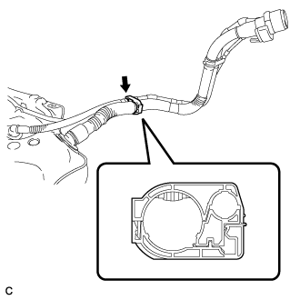
Install the No. 1 fuel tank filler pipe support in the position shown in the illustration.
FUEL TANK > INSTALLATION |
| 1. INSTALL NO. 1 FUEL TANK FILLER PIPE SUPPORT |
|
Install the No. 1 fuel tank filler pipe support in the position shown in the illustration.
| 2. INSTALL NO. 2 FUEL TANK FILLER PIPE SUPPORT |
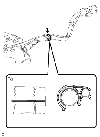 |
Install the No. 2 fuel tank filler pipe support in the position shown in the illustration.
| *a | Clamp Position |
| 3. INSTALL FUEL HOSE CLAMP |
Install the fuel hose clamp onto the fuel tank assembly.
| 4. REMOVE NO. 1 CANISTER OUTLET HOSE SUB-ASSEMBLY |
Install the No. 1 canister outlet hose sub-assembly to the fuel tank assembly.
| 5. INSTALL FUEL TANK MAIN TUBE SUB-ASSEMBLY |
Install the fuel tank main tube onto the fuel tank assembly.
| 6. INSTALL FUEL TANK ASSEMBLY |
Clean and degrease the bolt holes.
Using an engine lifter, set the fuel tank assembly in the installation position.
Install the fuel tank assembly with 4 new bolts.
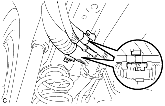 |
Install the 2 fuel hoses to the position shown in the illustration.
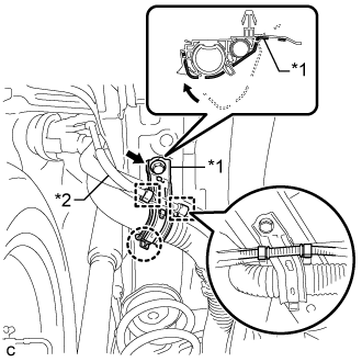 |
Install the fuel tank filler pipe flange plate as shown in the illustration.
| *1 | Fuel Tank Filler Pipe Flange Plate |
| *2 | Air Tube |
Install the bolt.
Install the air tube as shown in the illustration.
| 7. CONNECT FUEL TANK MAIN TUBE SUB-ASSEMBLY |
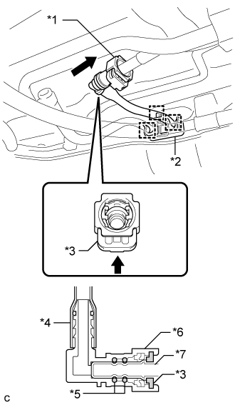 |
Align the fuel tube connector with the fuel pipe, connect the fuel tube connector and push the retainer in until the retainer makes a "click" sound to lock the claws of the retainer.
| *1 | Fuel Tank Main Tube Sub-assembly |
| *2 | Fuel Tank Pipe Setting Holder |
| *3 | Retainer |
| *4 | Nylon Tube |
| *5 | O-ring |
| *6 | Fuel Tube Connector |
| *7 | Fuel Pipe |
Engage the 3 clamps and install the fuel tank pipe setting holder.
| 8. INSTALL NO. 1 FUEL TUBE PROTECTOR |
Install the No. 1 fuel tube protector to the fuel tube connector.
| 9. CONNECT NO. 2 FUEL EMISSION TUBE |
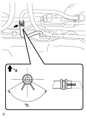 |
Connect the No. 2 fuel emission tube, then fit it with the clip as shown in the illustration.
| *a | Up |
| *b | 120° |
| 10. INSTALL NO. 1 FUEL TANK PROTECTOR SUB-ASSEMBLY |
Install the No. 1 fuel tank protector sub-assembly with the bolt and clip.
| 11. INSTALL FRONT NO. 4 FLOOR HEAT INSULATOR |
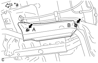 |
Install the front No. 4 floor heat insulator with the 2 nuts.
| *a | Front |
| 12. INSTALL FUEL TANK CAP ASSEMBLY |
| 13. INSTALL FUEL SUCTION TUBE WITH PUMP AND GAUGE ASSEMBLY |
| 14. ADD FUEL |