 |
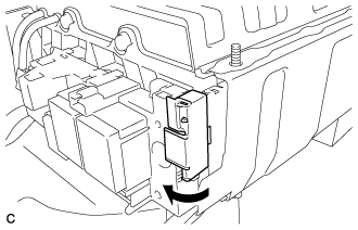
Connect the terminal cover.
- NOTICE:
- The terminal cover should be connected securely.
HV BATTERY > INSTALLATION |
| 1. INSTALL NO. 1 HYBRID BATTERY PACKING |
Connect the 2 wire harnesses to the No. 1 hybrid battery packing.
Install the No. 1 hybrid battery packing with the 2 clamps.
| 2. INSTALL UPPER HYBRID BATTERY COVER SUB-ASSEMBLY |
Install the upper hybrid battery cover sub-assembly with the 5 nuts.
| 3. INSTALL NO. 1 HYBRID BATTERY COVER INTAKE DUCT |
Install the No. 1 hybrid battery cover intake duct with the clip.
Install the HV battery thermistor to the No. 1 hybrid battery cover intake duct.
| 4. INSTALL HYBRID BATTERY JUNCTION BLOCK ASSEMBLY |
Install the hybrid battery junction block assembly with the 3 bolts.
Connect the connector to the hybrid battery junction block assembly.
Using an insulated tool, install the 2 bolts.
|
Connect the terminal cover.
| 5. INSTALL NO. 2 HYBRID BATTERY SHIELD SUB-ASSEMBLY |
Install the No. 2 hybrid battery shield sub-assembly with the 2 bolts and nut.
| 6. INSTALL BATTERY SMART UNIT |
w/o Wiring Harness Protector:
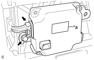 |
Install the battery smart unit to the HV battery with the bolt.
| *a | Red Label |
Connect the battery smart unit connector.
w/ Wiring Harness Protector:
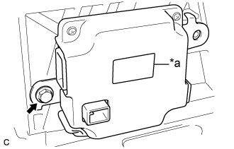 |
Install the battery smart unit to the HV battery with the bolt.
| *a | Red Label |
Install the wiring harness protector to the battery smart unit connector.
Connect the battery smart unit connector.
Engage the 2 claws to install the wiring harness protector cover to the battery smart unit connector.
| 7. INSTALL NO. 2 HYBRID VEHICLE BATTERY CARRIER BRACKET SUB-ASSEMBLY |
Install the No. 2 hybrid vehicle battery carrier bracket sub-assembly with the bolt and 2 nuts.
Engage the 3 clamps.
Connect the battery smart unit connector.
| 8. INSTALL NO. 1 HYBRID BATTERY SHIELD SUB-ASSEMBLY |
Install the No. 1 hybrid battery shield sub-assembly with the 2 bolts and 2 nuts.
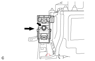 |
Install the electric vehicle battery plug with the bolt as shown in the illustration.
| 9. INSTALL HYBRID BATTERY SERVICE PLUG COVER |
Install the hybrid battery service plug cover with the 2 nuts.
| 10. INSTALL HV BATTERY |
Install the HV battery with the 2 bolts and 2 nuts.
Install the 2 clips.
| 11. CONNECT FRAME WIRE |
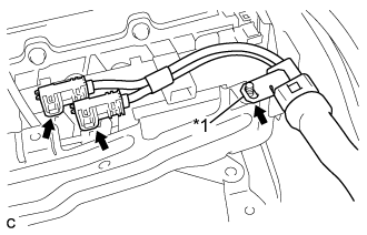 |
Connect the 2 connectors.
| *1 | Shielded Wire Ground |
Connect the shielded wire ground.
| 12. CONNECT WIRE HARNESS |
Connect the 2 connectors and 3 clamps.
| 13. INSTALL NO. 3 INDOOR ELECTRICAL KEY ANTENNA ASSEMBLY |
Connect the connector.
Engage the 2 clamps to install the No. 3 indoor electrical key antenna assembly.
| 14. INSTALL NO. 1 HYBRID VEHICLE BATTERY COVER PANEL LH |
Install the No. 1 hybrid vehicle battery cover panel LH with the 4 nuts.
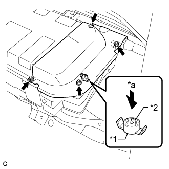 |
Install the battery cover lock striker, then push the button to lock it.
| *1 | Battery Cover Lock Striker |
| *2 | Button |
| *a | Push |
| 15. INSTALL BATTERY COOLING BLOWER ASSEMBLY |
Install the battery cooling blower assembly with the 2 bolts and nut.
Connect the battery cooling blower assembly connector and engage the clamp to the battery cooling blower assembly.
| 16. INSTALL NO. 1 HYBRID BATTERY EXHAUST DUCT |
Install the No. 1 hybrid battery exaust duct with the clip.
| 17. INSTALL REAR SEAT CUSHION LEG SUB-ASSEMBLY |
Temporarily install the rear seat cushion leg sub-assembly with the 4 bolts.
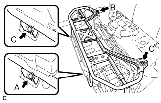 |
Tighten the bolt (A).
Tighten the bolt (B).
Tighten the 2 bolts (C).
| 18. INSTALL REAR SEAT CUSHION ASSEMBLY (for Separate Type Seatback) |
Place the rear seat cushion assembly in the cabin.
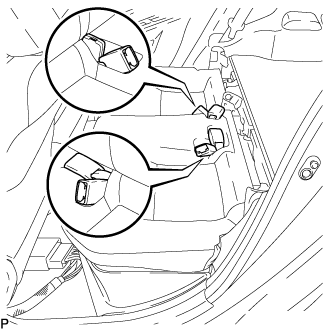 |
Push out the seat belt buckles from the back of the rear seat cushion assembly so that they are positioned as shown in the illustration.
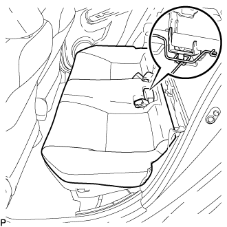 |
Engage the hook of the rear seat cushion assembly to the CRS anchor bracket.
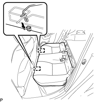 |
Engage the 2 rear seat cushion lock hooks to install the rear seat cushion assembly as shown in the illustration.
Confirm that the seat cushion is firmly installed.
Engage the 2 clips.
| 19. INSTALL REAR SEAT CUSHION ASSEMBLY (for Bench Type Seatback) |
Place the rear seat cushion assembly in the cabin.
|
Push out the seat belt buckles from the back of the rear seat cushion assembly so that they are positioned as shown in the illustration.
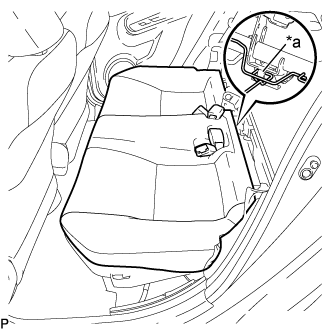 |
Engage the hook of the rear seat cushion assembly to the CRS anchor bracket.
| *a | Hook |
|
Engage the 2 rear seat cushion lock hooks to install the rear seat cushion assembly as shown in the illustration.
Confirm that the seat cushion is firmly installed.
Engage the 2 clips.
| 20. INSTALL SERVICE PLUG GRIP |