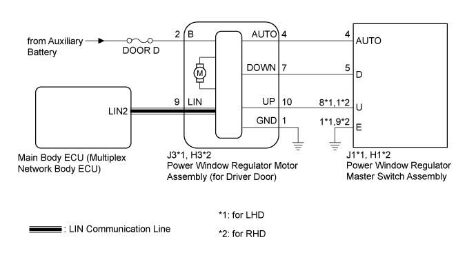
DTC B2312 Power Window Switch Malfunction |
| DTC No. | DTC Detection Condition | Trouble Area |
| B2312 |
|
|
| 1.CHECK DTC OUTPUT |
Clear the DTC (Click here).
Check for DTCs (Click here).
|
| ||||
| OK | ||
 | ||
| ||
| 2.READ VALUE USING INTELLIGENT TESTER (DRIVER DOOR WINDOW MOTOR) |
Connect the intelligent tester to the DLC3.
Turn the power switch to on (IG).
Turn the intelligent tester on.
Enter the following menus: Body / D-Door Motor / Data List.
Read the Data List according to the display on the intelligent tester.
| Tester Display | Measurement Item/Range | Normal Condition | Diagnostic Note |
| D Door P/W Auto SW | Driver door power window auto switch signal / ON or OFF | ON: Driver door power window auto switch operated OFF: Driver door power window auto switch not operated | - |
| D Door P/W Up SW | Driver door power window manual up switch signal / ON or OFF | ON: Driver door power window manual up switch operated OFF: Driver door power window manual up switch not operated | - |
| D Door P/W Down SW | Driver door power window manual down switch signal / ON or OFF | ON: Driver door power window manual down switch operated OFF: Driver door power window manual down switch not operated | - |
|
| ||||
| OK | ||
| ||
| ||
| 3.CHECK HARNESS AND CONNECTOR (POWER WINDOW REGULATOR MASTER SWITCH - POWER WINDOW REGULATOR MOTOR (FOR DRIVER DOOR)) |
Disconnect the power window regulator master switch assembly connector.
Disconnect the power window regulator motor assembly (for driver door) connector.
Measure the resistance according to the value(s) in the table below.
| Tester Connection | Condition | Specified Condition |
| J1-8 (U) - Body ground | Always | 10 kΩ or higher |
| J1-5 (D) - Body ground | Always | 10 kΩ or higher |
| J1-4 (AUTO) - Body ground | Always | 10 kΩ or higher |
| J3-10 (UP) - Body ground | Always | 10 kΩ or higher |
| J3-7 (DOWN) - Body ground | Always | 10 kΩ or higher |
| J3-4 (AUTO) - Body ground | Always | 10 kΩ or higher |
| Tester Connection | Condition | Specified Condition |
| H1-1 (U) - Body ground | Always | 10 kΩ or higher |
| H1-5 (D) - Body ground | Always | 10 kΩ or higher |
| H1-4 (AUTO) - Body ground | Always | 10 kΩ or higher |
| H3-10 (UP) - Body ground | Always | 10 kΩ or higher |
| H3-7 (DOWN) - Body ground | Always | 10 kΩ or higher |
| H3-4 (AUTO) - Body ground | Always | 10 kΩ or higher |
|
| ||||
| OK | |
 |
| 4.INSPECT POWER WINDOW REGULATOR MASTER SWITCH ASSEMBLY |
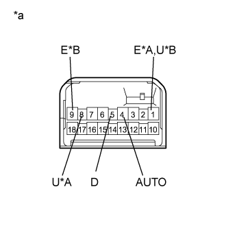 |
Remove the power window regulator master switch assembly (Click here).
Measure the resistance according to the value(s) in the table below.
| Tester Connection | Switch Condition | Specified Condition |
| 8 (U) - 1 (E) | Released | 10 kΩ or higher |
| 8 (U) - 4 (AUTO) | Released | 10 kΩ or higher |
| 4 (AUTO) - 1 (E) | Released | 10 kΩ or higher |
| 5 (D) - 1 (E) | Released | 10 kΩ or higher |
| 4 (AUTO) - 5 (D) | Released | 10 kΩ or higher |
| Tester Connection | Switch Condition | Specified Condition |
| 1 (U) - 9 (E) | Released | 10 kΩ or higher |
| 1 (U) - 4 (AUTO) | Released | 10 kΩ or higher |
| 4 (AUTO) - 9 (E) | Released | 10 kΩ or higher |
| 5 (D) - 9 (E) | Released | 10 kΩ or higher |
| 4 (AUTO) - 5 (D) | Released | 10 kΩ or higher |
| *A | for LHD |
| *B | for RHD |
| *a | Component without harness connected (Power Window Regulator Master Switch Assembly) |
|
| ||||
| OK | ||
| ||
| ||

