| B |  |
| Go to step 5 |
DTC P2511-149 HV CPU Power Relay Sense Circuit Intermittent No Continuity |
| DTC No. | INF Code | DTC Detection Condition | Trouble Area |
| P2511 | 149 | When the power switch is on (READY), the hybrid vehicle control ECU is reset. |
|
| 1.CHECK AUXILIARY BATTERY TERMINAL |
Confirm whether the auxiliary battery terminals have been disconnected recently.
| Result | Proceed to |
| Terminals have been disconnected. | A |
| Terminals have not been disconnected. | B |
|
| ||||
| A | |
 |
| 2.CONFIRM THAT MASTER WARNING LIGHT |
Turn the power switch on (READY) from off.
Confirm that the master warning light illuminates.
| Result | Proceed to |
| Master warning light illuminates. | A |
| Master warning light does not illuminates. | B |
Turn the power switch off.
|
| ||||
| A | |
|
| 3.CLEAR DTC |
Connect the intelligent tester to the DLC3.
Turn the power switch on (IG).
Enter the following menus: Powertrain / Hybrid Control / DTC.
Read and record the DTCs and freeze frame data.
Clear the DTCs and freeze frame data.
Turn the power switch off.
| NEXT | |
|
| 4.CHECK DTC OUTPUT (HYBRID CONTROL) |
Connect the intelligent tester to the DLC3.
Turn the power switch on (IG).
Enter the following menus: Powertrain / Hybrid Control / DTC.
Check if DTCs are output.
| Result | Proceed to |
| DTC P2511-149 is output again. | A |
| DTCs other than P2511-149 are also output. | B |
Turn the power switch off.
|
| ||||
| A | |
|
| 5.CHECK AUXILIARY BATTERY TERMINAL (CONTACT PROBLEM) |
Check the connection of the auxiliary battery terminal.
|
| ||||
| OK | |
|
| 6.CHECK CONNECTOR CONNECTION CONDITION (HYBRID VEHICLE CONTROL ECU CONNECTOR) |
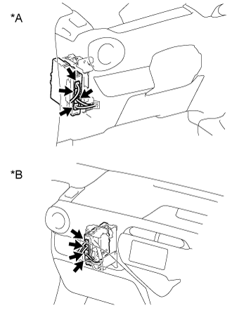 |
Check the connector connections and contact pressure of the relevant terminals for the hybrid vehicle control ECU connectors (Click here).
| *A | for LHD |
| *B | for RHD |
|
| ||||
| OK | |
|
| 7.CHECK HARNESS AND CONNECTOR (HYBRID VEHICLE CONTROL ECU - IGCT RELAY) |
Remove the IGCT relay from the No. 2 engine room relay block and No. 2 junction block assembly.
Disconnect connectors A71 and A72 from hybrid vehicle control ECU.
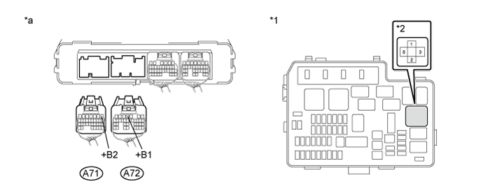
| *1 | No. 2 Engine Room Relay Block and No. 2 Junction Block Assembly | *2 | IGCT Relay |
| *a | Rear view of wire harness connector (to Hybrid Vehicle Control ECU) | - | - |
Measure the resistance according to the value(s) in the table below.
| Tester Connection | Switch Condition | Specified Condition |
| A72-4 (+B1) - 5 (IGCT relay) | Power switch off | Below 1 Ω |
| A71-1 (+B2) - 5 (IGCT relay) | Power switch off | Below 1 Ω |
Install the IGCT relay.
Connect the hybrid vehicle control ECU connectors.
|
| ||||
| OK | |
|
| 8.CHECK FOR INTERMITTENT PROBLEMS |
Check for intermittent problems (Click here).
Check the connection and terminal contact pressure of connectors and wire harnesses between the hybrid vehicle control ECU and the No. 2 engine room relay block and No. 2 junction block assembly.
When the power switch is on (READY), jiggle the connectors and wire harnesses between the hybrid vehicle control ECU and the No. 2 engine room relay block and No. 2 junction block assembly.
| Result | Proceed to |
| Problem symptom does not recur. | A |
| Problem symptom recurs. | B |
|
| ||||
| A | ||
 | ||
| ||
