CAN COMMUNICATION SYSTEM > SYSTEM DIAGRAM |
| OVERALL CAN BUS DIAGRAM (for LHD) |
Control system CAN is composed of 2 buses.
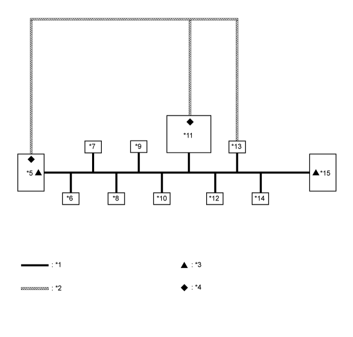
| *1 | V Bus | *2 | Sub Bus 15 |
| *3 | V Bus Terminating Resistor | *4 | Sub Bus 15 Terminating Resistor |
| *5 | ECM (for V Bus and Sub Bus 15) | *6 | Main Body ECU (Multiplex Network Body ECU) (for V Bus) |
| *7 | Airbag Sensor Assembly (for V Bus) | *8 | Spiral Cable with Sensor Sub-assembly (Steering Sensor) (for V Bus) |
| *9 | Power Steering ECU Assembly (for V Bus) | *10 | Air Conditioning Amplifier Assembly (for V Bus) |
| *11 | Power Management Control ECU (for V Bus and Sub Bus 15) | *12 | Smart Key ECU Assembly (Certification ECU) (for V Bus) |
| *13 | Brake Booster with Master Cylinder Assembly (Skid Control ECU) (for V Bus and Sub Bus 15) | *14 | DLC3 (for V Bus) |
| *15 | Combination Meter Assembly (for V Bus) | - | - |
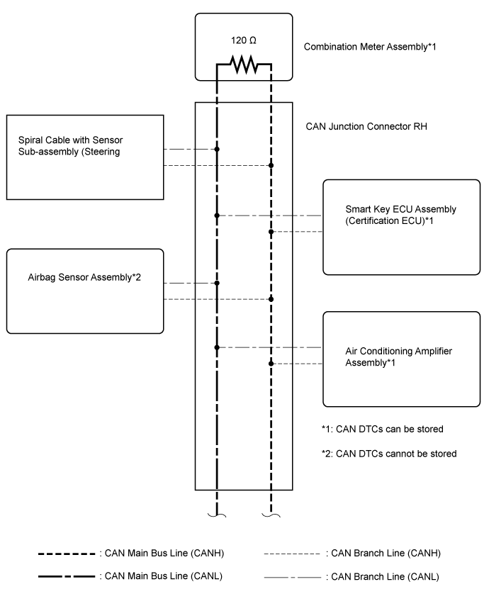
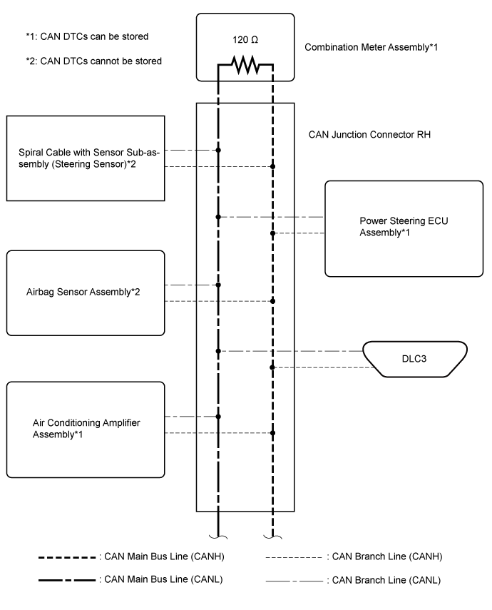
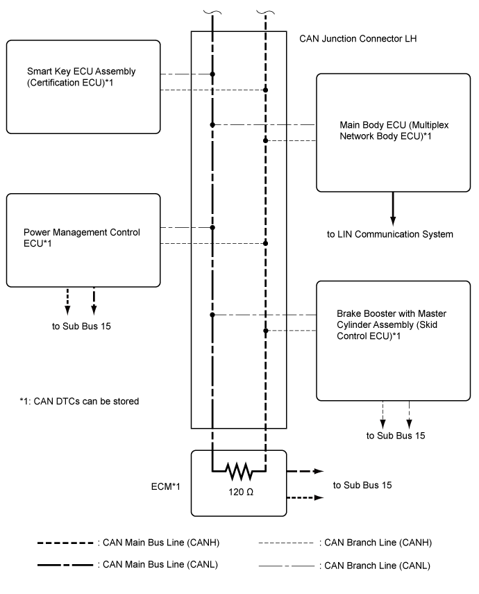
| V BUS (for LHD) |


| OVERALL CAN BUS DIAGRAM (for RHD) |
Control system CAN is composed of 2 buses.

| *1 | V Bus | *2 | Sub Bus 15 |
| *3 | V Bus Terminating Resistor | *4 | Sub Bus 15 Terminating Resistor |
| *5 | ECM (for V Bus and Sub Bus 15) | *6 | Main Body ECU (Multiplex Network Body ECU) (for V Bus) |
| *7 | Airbag Sensor Assembly (for V Bus) | *8 | Spiral Cable with Sensor Sub-assembly (Steering Sensor) (for V Bus) |
| *9 | Power Steering ECU Assembly (for V Bus) | *10 | Air Conditioning Amplifier Assembly (for V Bus) |
| *11 | Power Management Control ECU (for V Bus and Sub Bus 15) | *12 | Smart Key ECU Assembly (Certification ECU) (for V Bus) |
| *13 | Brake Booster with Master Cylinder Assembly (Skid Control ECU) (for V Bus and Sub Bus 15) | *14 | DLC3 (for V Bus) |
| *15 | Combination Meter Assembly (for V Bus) | - | - |
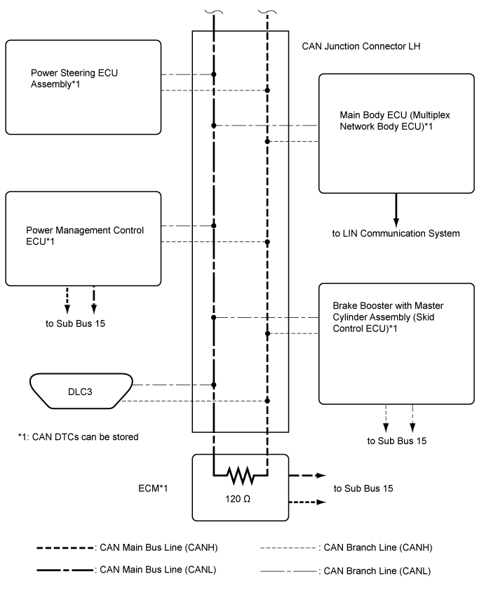
| V BUS (for RHD) |


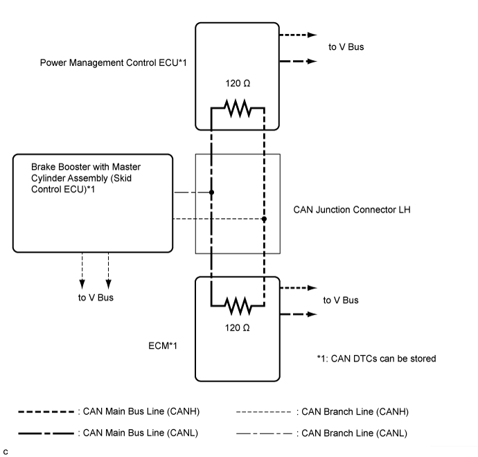
| SUB BUS 15 |