 |
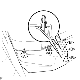
Using a clip remover, remove the 2 clips <A>.
REAR DOOR > DISASSEMBLY |
| 1. PRECAUTION |
| 2. REMOVE FRONT FLOOR COVER RH |
|
Using a clip remover, remove the 2 clips <A>.
Disengage the 3 clips <B>.
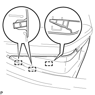 |
Disengage the 3 guides and remove the front floor cover RH.
| 3. DISCONNECT CABLE FROM NEGATIVE AUXILIARY BATTERY TERMINAL |
| 4. REMOVE REAR DOOR FRAME GARNISH |
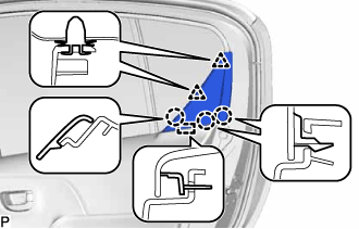 |
Disengage the 2 clips and 3 claws.
Disengage the guide and remove the rear door frame garnish.
| 5. REMOVE REAR POWER WINDOW REGULATOR SWITCH ASSEMBLY WITH REAR DOOR ARMREST BASE PANEL |
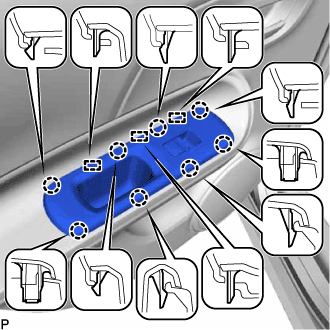 |
Disengage the 8 claws and 3 guides.
Disconnect the connector and remove the rear power window regulator switch assembly with rear door armrest base panel.
| 6. REMOVE REAR DOOR TRIM BOARD SUB-ASSEMBLY |
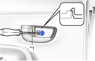 |
Using a screwdriver with its tip wrapped in protective tape, disengage the claw and open the cover.
| *1 | Protective Tape |
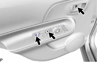 |
Remove the 3 screws.
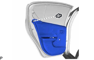 |
Disengage the clip.
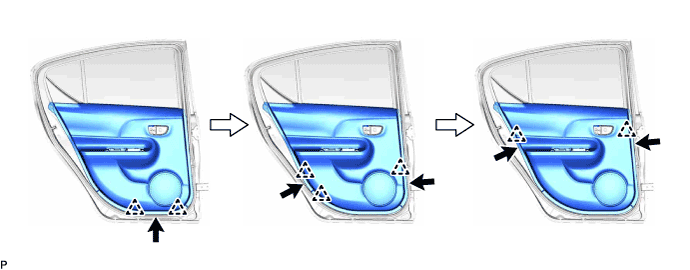
pull the rear door trim board sub-assembly at the position indicated in the illustration and disengage the 7 clips in the order shown in the illustration.
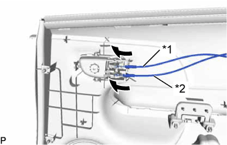 |
Disconnect the rear door lock remote control cable assembly and rear door inside locking cable assembly and remove the rear door trim board.
| *1 | Rear Door Inside Locking Cable Assembly |
| *2 | Rear Door Lock Remote Control Cable Assembly |
| 7. REMOVE REAR DOOR INSIDE HANDLE SUB-ASSEMBLY |
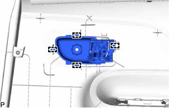 |
Disengage the 4 guides and remove the rear door inside handle sub-assembly.
| 8. REMOVE REAR DOOR GLASS INNER WEATHERSTRIP |
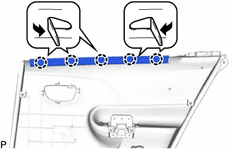 |
Disengage the 5 claws and remove the rear door glass inner weatherstrip as shown in the illustration.
| 9. REMOVE REAR SPEAKER ASSEMBLY |
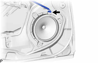 |
Disconnect the connector.
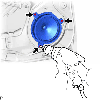 |
Using a drill bit with a diameter of less than 5 mm (0.197 in.), drill out the 3 rivet heads and remove the rear speaker assembly.
Continue drilling and push out the remaining rivet fragments.
Using a vacuum cleaner, remove the rivet fragments and shavings from the inside of the door.
| 10. REMOVE REAR DOOR SERVICE HOLE COVER |
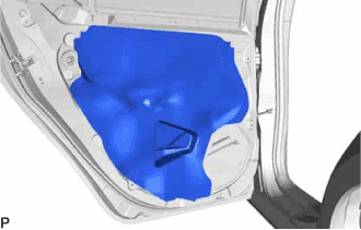 |
Remove the rear door service hole cover.
| 11. REMOVE REAR DOOR CHECK ASSEMBLY |
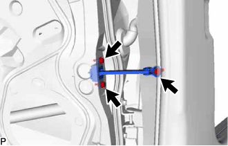 |
Remove the 3 bolts and the rear door check assembly.
| 12. REMOVE REAR DOOR WEATHERSTRIP |
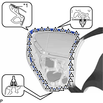 |
Using a clip remover, disengage the 30 clips.
| *1 | Double-sided Tape |
Remove the rear door weatherstrip.
| 13. REMOVE REAR DOOR GLASS RUN |
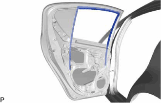 |
Remove the rear door glass run.
| 14. REMOVE REAR DOOR WINDOW DIVISION BAR SUB-ASSEMBLY |
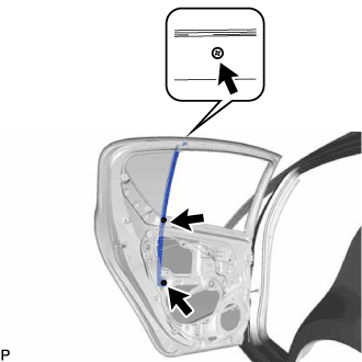 |
Remove the 2 bolts and screw, and remove the rear door window division bar sub-assembly.
| 15. REMOVE REAR DOOR GLASS SUB-ASSEMBLY |
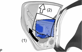 |
Slide the lower section of the rear door glass and disengage the rear door glass from the rear window regulator sub-assembly.
Remove the rear door glass sub-assembly as indicated by the arrows in the order shown in the illustration.
| 16. REMOVE REAR DOOR GLASS CHANNEL SUB-ASSEMBLY |
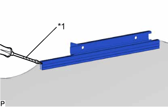 |
Using a screwdriver with its tip wrapped in protective tape, remove the rear door glass channel sub-assembly.
| *1 | Protective Tape |
| 17. REMOVE REAR DOOR GLASS CHANNEL FILLER |
Remove the rear door glass channel filler.
| 18. REMOVE REAR DOOR WINDOW REGULATOR ASSEMBLY |
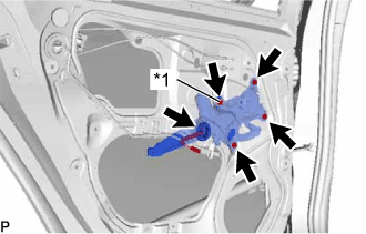 |
Disconnect the connector.
| *1 | Temporary Bolt |
Loosen the temporary bolt.
Remove the 3 bolts and rear door window regulator assembly.
Remove the temporary bolt from the rear door window regulator assembly.
| 19. REMOVE POWER WINDOW REGULATOR MOTOR ASSEMBLY |
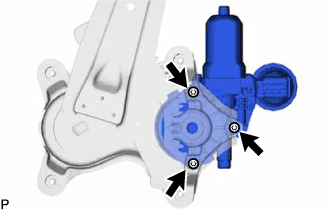 |
Using a T25 "TORX" socket wrench, remove the 3 screws and power window regulator motor assembly.
| 20. REMOVE REAR DOOR GLASS OUTER WEATHERSTRIP ASSEMBLY |
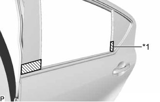 |
Apply protective tape to the door panel in the area around the rear door glass outer weatherstrip assembly.
| *1 | Protective Tape |
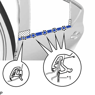 |
Using a screwdriver with the tip wrapped with protective tape, disengage the 4 claws.
| *1 | Protective Tape |
Disengage the guide and remove the rear door glass outer weatherstrip assembly.
| 21. REMOVE REAR DOOR QUARTER WINDOW GLASS |
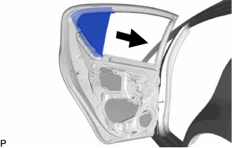 |
Slide the rear door quarter window glass as shown in the illustration and remove the rear door quarter window glass with rear door quarter window weatherstrip.
| 22. REMOVE REAR DOOR LOCK ASSEMBLY |
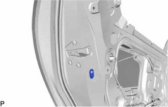 |
Remove the rear door lock child protection cover.
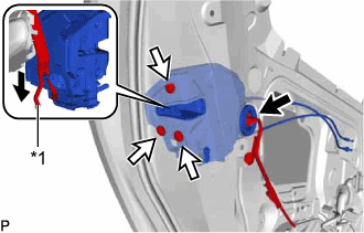 |
Disconnect the connector.
Using a T30 "TORX" socket wrench, remove the 3 screws.
Move the rear door lock assembly downward and pull the release plate out of the rear door outside handle frame.
| *1 | Release Plate |
When reusing the rear door lock assembly:
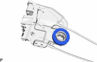 |
Remove the door lock wiring harness seal from the rear door lock assembly.
| 23. REMOVE REAR DOOR LOCK REMOTE CONTROL CABLE ASSEMBLY |
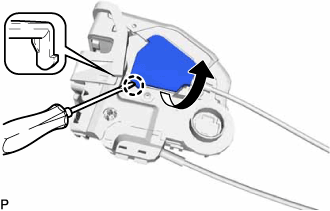 |
Using a screwdriver, disengage the claw as shown in the illustration.
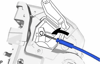 |
Remove the rear door lock remote control cable assembly as shown in the illustration.
| 24. REMOVE REAR DOOR INSIDE LOCKING CABLE ASSEMBLY |
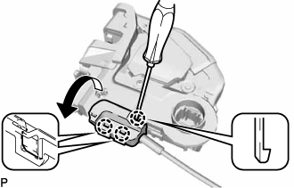 |
Using a screwdriver, disengage the 3 claws as shown in the illustration.
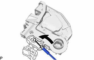 |
Remove the rear door inside locking cable assembly as shown in the illustration.
| 25. REMOVE REAR DOOR OUTSIDE HANDLE COVER |
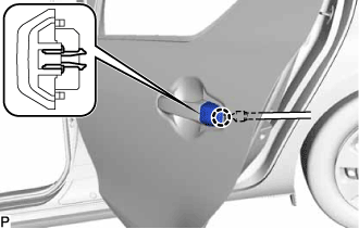 |
Using a "TORX" socket wrench T30, loosen the screw.
Disengage the claw and remove the rear door outside handle cover.
| 26. REMOVE REAR DOOR OUTSIDE HANDLE ASSEMBLY |
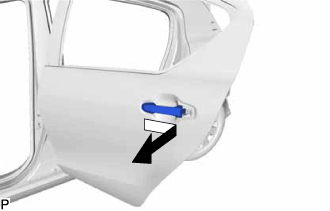 |
Remove the rear door outside handle assembly as shown in the illustration.
| 27. REMOVE REAR DOOR OUTSIDE HANDLE FRONT PAD |
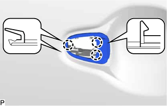 |
Disengage the 3 claws to remove the rear door outside handle front pad.
| 28. REMOVE REAR DOOR OUTSIDE HANDLE REAR PAD |
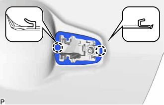 |
Disengage the 2 claws to remove the rear door outside handle rear pad.
| 29. REMOVE REAR DOOR OUTSIDE HANDLE FRAME SUB-ASSEMBLY |
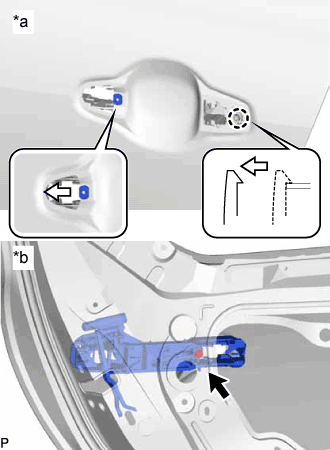 |
Using a T30 "TORX" socket wrench, loosen the screw.
| *a | Outside |
| *b | Inside |
Slide the rear door outside handle frame sub-assembly to disengage the door handle nut and claw of the rear door outside handle frame sub-assembly, and then remove the rear door outside handle frame sub-assembly.
| 30. REMOVE NO. 2 BLACK OUT TAPE |
Using a heat light, heat the No. 2 black out tape and vehicle body.
| Item | Temperature |
| No. 2 Black Out Tape and Vehicle Body | 40 to 60°C (104 to 140°F) |
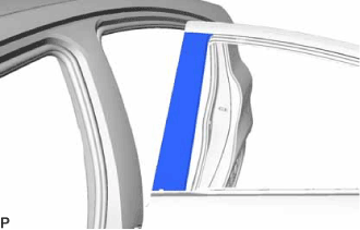 |
Pull back on one of the ends of the No. 2 black out tape to remove it.