LIN COMMUNICATION SYSTEM > TERMINALS OF ECU |
| CHECK INSTRUMENT PANEL JUNCTION BLOCK ASSEMBLY AND MAIN BODY ECU (MULTIPLEX NETWORK BODY ECU) |
Disconnect the MB main body ECU (multiplex network body ECU) connector.
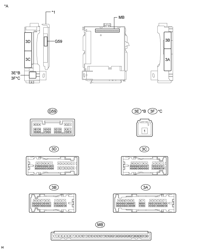
| *A | Main body ECU (multiplex network body ECU) with 1 connector | *B | for LHD |
| *C | for RHD | - | - |
| *1 | Main body ECU (multiplex network body ECU) | - | - |
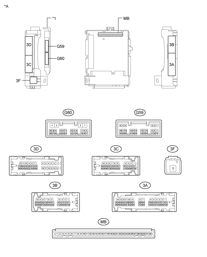
| *A | Main body ECU (multiplex network body ECU) with 2 connectors | - | - |
| *1 | Main body ECU (multiplex network body ECU) | - | - |
Measure the voltage and resistance according to the value(s) in the table below.
| Tester Connection | Wiring Color | Terminal Description | Condition | Specified Condition |
| MB-30 (BECU) - Body ground | - | Auxiliary battery power supply | Power switch off | 11 to 14 V |
| MB-32 (IG) - Body ground | - | IG power supply | Power switch on (IG) | 11 to 14 V |
| MB-29 (ACC) - Body ground | - | ACC power supply | Power switch on (ACC) | 11 to 14 V |
| MB-11 (GND1) - Body ground | - | Ground | Always | Below 1 Ω |
Reinstall the main body ECU (multiplex network body ECU) to the instrument panel junction block assembly.
Check for pulses according to the value(s) in the table below.
| Tester Connection | Wiring Color | Terminal Description | Condition | Specified Condition |
| 3B-12 (LIN2) - 3B-8 (GND1) | B - W-B | LIN communication line | Power switch on (IG) | Pulse generation |

| CHECK POWER WINDOW REGULATOR MOTOR ASSEMBLY (for Driver Door) |
Disconnect the J3*1 or H3*2 power window regulator motor assembly (for driver door) connector.

| *A | for LHD | *B | for RHD |
Measure the voltage and resistance according to the value(s) in the table below.
| Tester Connection | Wiring Color | Terminal Description | Condition | Specified Condition |
| J3-2 (B) - J3-1 (GND) | LA-G - LA | Auxiliary battery power supply | Power switch off | 11 to 14 V |
| J3-1 (GND) - Body ground | LA - Body ground | Ground | Always | Below 1 Ω |
| Tester Connection | Wiring Color | Terminal Description | Condition | Specified Condition |
| H3-2 (B) - H3-1 (GND) | LA-LG - LA | Auxiliary battery power supply | Power switch off | 11 to 14 V |
| H3-1 (GND) - Body ground | LA - Body ground | Ground | Always | Below 1 Ω |
Reconnect the J3*1 or H3*2 power window regulator motor assembly (for driver door) connector.
Check for pulses according to the value(s) in the table below.
| Tester Connection | Wiring Color | Terminal Description | Condition | Specified Condition |
| J3-9 (LIN) - J3-1 (GND) | B - LA | LIN communication line | Power switch on (IG) | Pulse generation |
| Tester Connection | Wiring Color | Terminal Description | Condition | Specified Condition |
| H3-9 (LIN) - H3-1 (GND) | B - LA | LIN communication line | Power switch on (IG) | Pulse generation |
| CHECK CERTIFICATION ECU (SMART KEY ECU ASSEMBLY) |
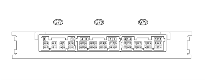
Disconnect the G77 certification ECU (smart key ECU assembly) connector.

Measure the voltage and resistance according to the value(s) in the table below.
| Tester Connection | Wiring Color | Terminal Description | Condition | Specified Condition |
| G77-2 (+B) - G77-11 (E) | B - W-B | Auxiliary battery power supply | Power switch off | 11 to 14 V |
| G79-5 (IG) - G77-11 (E) | V - W-B | IG power supply | Power switch on (IG) | 11 to 14 V |
| Power switch off | Below 1 Ω | |||
| G77-11 (E) - Body ground | W-B - Body ground | Ground | Always | Below 1 Ω |
Reconnect the G77 certification ECU (smart key ECU assembly) connector.
Measure the voltage and check for pulses according to the value(s) in the table below.
| Tester Connection | Wiring Color | Terminal Description | Condition | Specified Condition |
| G79-17 (LIN) - G77-11 (E) | LG - W-B | LIN communication line | Power switch on (IG) | Pulse generation |

| CHECK STEERING LOCK ECU (STEERING LOCK ACTUATOR ASSEMBLY) |
![]() |
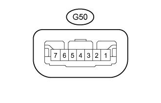
Disconnect the G50 steering lock ECU (steering lock actuator assembly) connector.
Measure the resistance and voltage according to the value(s) in the table below.
| Terminal No. (Symbol) | Wiring Color | Terminal Description | Condition | Specified Condition |
| G50-1 (GND) - Body ground | W-B - Body ground | Ground | Always | Below 1 Ω |
| G50-7 (B) - Body ground | GR - Body ground | Auxiliary battery power supply | Power switch off | 11 to 14 V |
| G50-6 (IG2) - Body ground | SB - Body ground | IG power supply | Power switch on (IG) | 11 to 14 V |
Reconnect the G50 steering lock ECU (steering lock actuator assembly) connector.
Measure the voltage and check for pulses according to the value(s) in the table below.
| Tester Connection | Wiring Color | Terminal Description | Condition | Specified Condition |
| G50-5 (LIN) - G50-1 (GND) | LG - W-B | LIN communication line | Power switch on (IG) | Pulse generation |
| CHECK ID CODE BOX (IMMOBILISER CODE ECU) |
Disconnect the G49 ID code box (immobiliser code ECU) connector.

Measure the voltage and resistance according to the value(s) in the table below.
| Tester Connection | Wiring Color | Terminal Description | Condition | Specified Condition |
| G49-1 (+B) - G49-5 (GND) | BE - W-B | Auxiliary battery power supply | Power switch off | 11 to 14 V |
| G49-5 (GND) - Body ground | W-B - Body ground | Ground | Always | Below 1 Ω |
Reconnect the G49 ID code box (immobiliser code ECU) connector.
Check for pulses according to the value(s) in the table below.
| Tester Connection | Wiring Color | Terminal Description | Condition | Specified Condition |
| G49-2 (LIN1) - G49-5 (GND) | LG - W-B | LIN communication line | Power switch on (IG) | Pulse generation |