 |
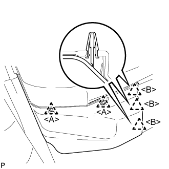
Using a clip remover, remove the 2 clips <A>.
POWER WINDOW REGULATOR MOTOR (for Front Door) > REMOVAL |
| 1. PRECAUTION |
| 2. REMOVE FRONT FLOOR COVER RH |
|
Using a clip remover, remove the 2 clips <A>.
Disengage the 3 clips <B>.
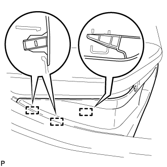 |
Disengage the 3 guides and remove the front floor cover RH.
| 3. DISCONNECT CABLE FROM NEGATIVE AUXILIARY BATTERY TERMINAL |
| 4. REMOVE POWER WINDOW REGULATOR MASTER SWITCH ASSEMBLY WITH FRONT DOOR ARMREST BASE PANEL (for Driver Side) |
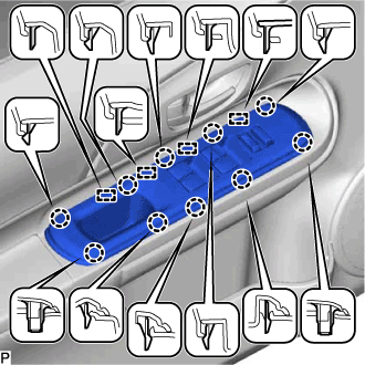 |
Disengage the 10 claws and 4 guides.
Disconnect the connector and remove the power window regulator master switch assembly with front door armrest base panel.
| 5. REMOVE POWER WINDOW REGULATOR SWITCH ASSEMBLY WITH FRONT DOOR ARMREST BASE PANEL (for Front Passenger Side) |
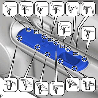 |
Disengage the 10 claws and 4 guides.
Disconnect the connector and remove the power window regulator switch assembly with front door armrest base panel.
| 6. REMOVE FRONT DOOR TRIM BOARD SUB-ASSEMBLY |
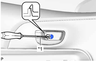 |
Using a screwdriver with its tip wrapped in protective tape, disengage the claw and open the cover.
| *1 | Protective Tape |
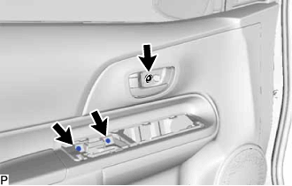 |
Remove the 3 screws.
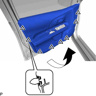 |
Disengage the 8 clips and remove the front door trim board sub-assembly as shown in the illustration.
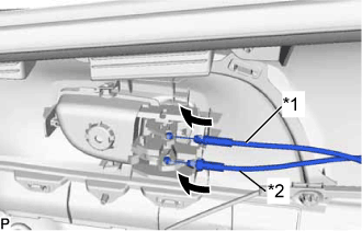 |
Disconnect the front door lock remote control cable assembly and front door inside locking cable from the front door trim board sub-assembly.
| *1 | Front Door Inside Locking Cable Assembly |
| *2 | Front Door Lock Remote Control Cable Assembly |
| 7. REMOVE FRONT NO. 2 SPEAKER ASSEMBLY |
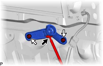 |
Disconnect the connector.
Remove the 2 screws and front No. 2 speaker assembly.
| 8. REMOVE FRONT DOOR SERVICE HOLE COVER |
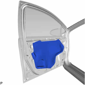 |
Remove the front door service hole cover.
| 9. REMOVE FRONT DOOR GLASS SUB-ASSEMBLY |
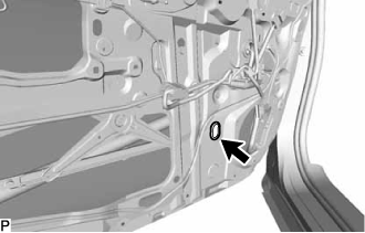 |
Remove the front door No. 2 service hole cover.
Connect the cable to the negative (-) auxiliary battery terminal and power window regulator master switch assembly and move the front door glass sub-assembly so that the door glass bolts can be seen.
Disconnect the negative (-) auxiliary battery terminal and power window regulator master switch assembly.
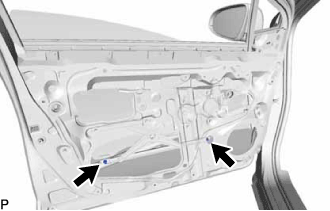 |
Remove the 2 bolts.
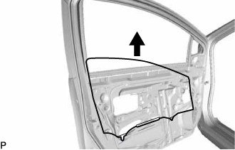 |
Remove the front door glass sub-assembly as shown in the illustration.
| 10. REMOVE FRONT DOOR WINDOW REGULATOR ASSEMBLY |
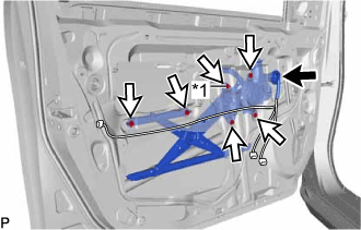 |
Disconnect the connector.
Loosen the temporary bolt.
| *1 | Temporary Bolt |
Remove the 5 bolts and front door window regulator assembly.
Remove the temporary bolt from the front door window regulator assembly.
| 11. REMOVE POWER WINDOW REGULATOR MOTOR ASSEMBLY |
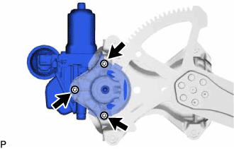 |
Using a T25 "TORX" socket wrench, remove the 3 screws and power window regulator motor assembly.