Home › Engine / Hybrid System › 1NZ-FXE ENGINE CONTROL › AIR FUEL RATIO SENSOR

AIR FUEL RATIO SENSOR > INSTALLATION

for Preparation Click here


1. INSTALL AIR FUEL RATIO SENSOR


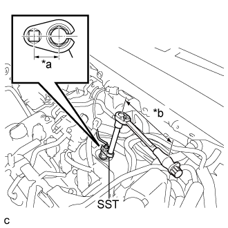
    A267411E01
  1. Using SST, install the air fuel ratio sensor.
    Text in Illustration 
    *a
    Fulcrum Length
    30 mm (1.18 in.)
    *b
    Fulcrum Length
    260 mm (10.2 in.)

    SST
    09224-00010  

    Torque:
    without SST:
    44 N*m{ 449 kgf*cm , 32 ft.*lbf }
    with SST:
    39 N*m{ 398 kgf*cm , 29 ft.*lbf }

    NOTICE:
    1. The "with SST" torque value is effective when using SST with a fulcrum length of 30 mm (1.18 in.) and a torque wrench with a fulcrum length of 260 mm (10.2 in.) (Click here).
    2. The "with SST" torque value is effective when SST is parallel to the torque wrench.

    HINT:
    Perform "Inspection After Repair" after replacing the air fuel ratio sensor (Click here).
  1. Connect the air fuel ratio sensor connector and 2 clamps.


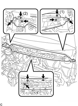
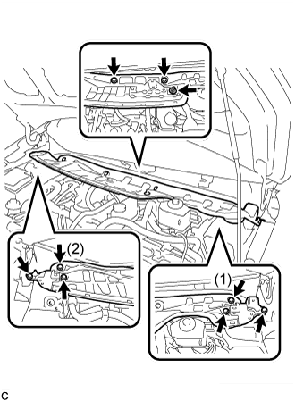
2. INSTALL OUTER COWL TOP PANEL SUB-ASSEMBLY (for LHD)


    C250015E01
  1. Install the outer cowl top panel sub-assembly with the 8 bolts and nut.

    Torque:
    Bolt:
    7.0 N*m{ 71 kgf*cm , 62 in.*lbf }
    Nut:
    12 N*m{ 122 kgf*cm , 9 ft.*lbf }

    NOTICE:
    Tighten the 2 bolts (1) and (2) first, and then tighten the rest of the bolts and nut.

  1. Engage the clamp to install the wire harness.


3. INSTALL OUTER COWL TOP PANEL SUB-ASSEMBLY (for RHD)


    C249838E01
  1. Install the outer cowl top panel sub-assembly with the 8 bolts and nut.

    Torque:
    Bolt:
    7.0 N*m{ 71 kgf*cm , 62 in.*lbf }
    Nut:
    12 N*m{ 122 kgf*cm , 9 ft.*lbf }

    NOTICE:
    Tighten the 2 bolts (1) and (2) first, and then tighten the rest of the bolts and nut.

  1. Engage the 3 clamps to install the wire harness.


4. INSTALL FRONT NO. 1 VENTILATOR SEAL (for LHD)
  1. Engage the clamp to install the front No. 1 ventilator seal to the outer cowl top panel sub-assembly.


5. INSTALL FRONT NO. 1 VENTILATOR SEAL (for RHD)
  1. Engage the clamp to install the front No. 1 ventilator seal to the outer cowl top panel sub-assembly.


6. INSTALL FRONT AIR SHUTTER SEAL (for LHD)
  1. Engage the clamp to install the front air shutter seal to the outer cowl top panel sub-assembly.


7. INSTALL FRONT AIR SHUTTER SEAL (for RHD)
  1. Engage the clamp to install the front air shutter seal to the outer cowl top panel sub-assembly.


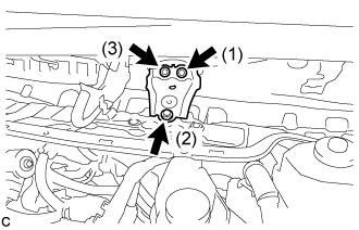
8. INSTALL INNER COWL TOP TO COWL BRACE (for LHD)


    C250011E01
  1. Install the inner cowl top to cowl brace to the outer cowl top panel sub-assembly with the 3 bolts.

    Torque:
    7.0 N*m{ 71 kgf*cm , 62 in.*lbf }

    NOTICE:
    Tighten the 3 bolts in the order shown in the illustration.


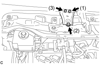
9. INSTALL INNER COWL TOP TO COWL BRACE (for RHD)


    C249834E01
  1. Install the inner cowl top to cowl brace to the outer cowl top panel sub-assembly with the 3 bolts.

    Torque:
    7.0 N*m{ 71 kgf*cm , 62 in.*lbf }

    NOTICE:
    Tighten the 3 bolts in the order shown in the illustration.


10. INSTALL WINDSHIELD WIPER MOTOR AND LINK ASSEMBLY
(Click here).