Home › Brake › BRAKE SYSTEM (OTHER) › BRAKE FLUID

BRAKE FLUID > BLEEDING

for Preparation Click here


CAUTION:
The intelligent tester must be used for air bleeding. If not used, the air bleeding will be incomplete, which is hazardous and may lead to an accident.

NOTICE:
  1. Perform air bleeding with the shift lever in P and the parking brake applied.
  2. As brake fluid may overflow when bleeding, do not stand the fluid can on the reservoir inlet.
  3. Perform air bleeding while maintaining the brake fluid level between the MIN and MAX lines on the brake fluid reservoir.
  4. Air bleeding will be difficult if the following occurs:
    1. The brake actuator hose (the hose between the brake booster pump assembly and brake fluid reservoir) is higher than the fluid level and air enters the hose.
    2. During the air bleeding procedure, air enters the brake booster pump while the pump motor is operating.
  5. While performing air bleeding, the accumulator pressure drop may cause a buzzer to sound. As there is no problem, continue with the operation.
  6. During air bleeding, DTCs for pressure sensor malfunctions, etc. may be stored. After air bleeding and if instructed in the procedures, clear the DTCs.
  7. Release the parking brake during the linear valve offset calibration procedure.
  8. Do not allow brake fluid to adhere to any painted surface such as the vehicle body. If brake fluid leaks onto any painted surface, immediately clean it off.
  9. When bleeding air, select the suitable work procedure according to the table below.
    Replaced/Installed Item
    Work Procedure
    Flexible hose (front/rear)
    Bleed brake line
    Front disc brake cylinder assembly
    Rear wheel cylinder assembly
    Brake booster pump assembly
    Bleed brake system
    Brake booster with master cylinder assembly
    Brake master cylinder reservoir assembly


1. BLEED BRAKE LINE


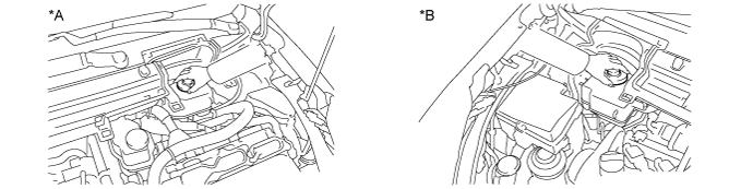
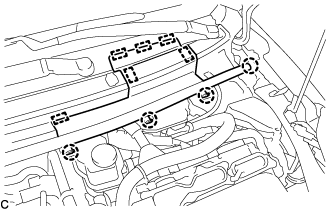
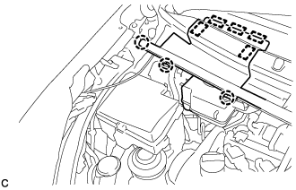
  1. Separate the center No. 1 cowl top ventilator louver.


      C250009
    1. for LHD:
      Disengage the 4 claws and 6 guides, and separate the center No. 1 cowl top ventilator louver.


    2. C249823
    3. for RHD:
      Disengage the 3 claws and 5 guides, and separate the center No. 1 cowl top ventilator louver.


  1. Bleed brake line.


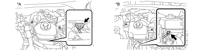
    1. Remove the brake master cylinder reservoir filler cap assembly.


      C256188E01


      Text in Illustration 
      *A
      for LHD
      *B
      for RHD

    2. Add brake fluid into the reservoir between the MAX and MIN lines on the brake fluid reservoir.

      Brake fluid:
      SAE J1703 or FMVSS No. 116 DOT3

    3. Connect the intelligent tester to the DLC3 and turn the power switch on (IG).

    4. Turn the intelligent tester on and enter the following menus: Chassis / ABS/VSC/TRC / Air Bleeding.

    5. Select "Usual air bleeding" on the intelligent tester display, and bleed air from the brake fluid following the instructions on the intelligent tester.

    6. After air bleeding, tighten each bleeder plug.

      Torque:
      front bleeder plug:
      8.3 N*m{ 85 kgf*cm , 73 in.*lbf }
      rear bleeder plug:
      8.5 N*m{ 87 kgf*cm , 75 in.*lbf }

    7. Clear the DTCs (Click here).

    8. Turn the intelligent tester off and turn the power switch off.

    9. Install the brake master cylinder reservoir filler cap.
  1. Inspect for brake fluid leaks.

  1. Install the center No. 1 cowl top ventilator louver.

    1. for LHD:
      Engage the 4 claws and 6 guides to install the center No. 1 cowl top ventilator louver.

    2. for RHD:
      Engage the 3 claws and 5 guides to install the center No. 1 cowl top ventilator louver.


2. BLEED BRAKE SYSTEM
  1. Remove the outer cowl top panel sub-assembly.

    1. for LHD: Click here
    2. for RHD: Click here


  1. Bleed the brake system.


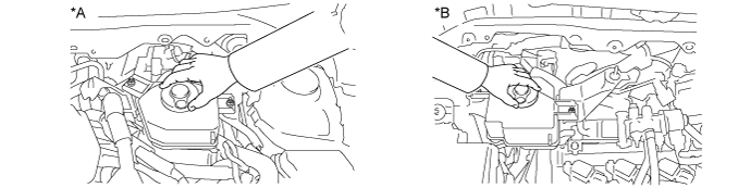
    1. Wait at least 2 minutes with the power switch off, and disconnect the reservoir level switch connector.


      C259395E01


      Text in Illustration 
      *A
      for LHD
      *B
      for RHD

      NOTICE:
      Do not depress the brake pedal or open/close the doors until the reservoir level switch connector is disconnected.

      HINT:
      This procedure is not required if the reservoir level switch connector has been disconnected.


    2. Remove the brake master cylinder reservoir filler cap assembly.


      C259396E01


      Text in Illustration 
      *A
      for LHD
      *B
      for RHD

    3. Add brake fluid into the reservoir between the MAX and MIN lines on the brake fluid reservoir.

      Brake fluid:
      SAE J1703 or FMVSS No. 116 DOT3

    4. Connect the intelligent tester to the DLC3 and turn the power switch on (IG).

    5. Turn the intelligent tester on and enter the following menus: Chassis / ABS/VSC/TRC / Air Bleeding.

    6. Select "ABS actuator has been replaced" on the intelligent tester display, and bleed air from the brake fluid following the instructions on the intelligent tester.

      NOTICE:
      Before following the instructions on the intelligent tester to perform linear valve offset calibration, release the parking brake. When calibration is complete, immediately apply the parking brake.


    7. C249825E01
    8. After air bleeding, tighten each bleeder plug.

      Torque:
      front bleeder plug:
      8.3 N*m{ 85 kgf*cm , 73 in.*lbf }
      rear bleeder plug:
      8.5 N*m{ 87 kgf*cm , 75 in.*lbf }
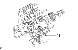
      stroke simulator bleeder plug:
      8.5 N*m{ 87 kgf*cm , 75 in.*lbf }

      HINT:
      The stroke simulator bleeder plug is positioned as shown in the illustration.

      Text in Illustration 
      *1
      Stroke Simulator Bleeder Plug

    9. Clear the DTCs (Click here).

    10. Turn the intelligent tester off and turn the power switch off.

    11. Install the brake master cylinder reservoir filler cap.
  1. Inspect for brake fluid leaks.

  1. Install the outer cowl top panel sub-assembly.

    1. for LHD: Click here
    2. for RHD: Click here