Home › Brake › BRAKE SYSTEM (OTHER) › BRAKE BOOSTER PUMP (for LHD)

BRAKE BOOSTER PUMP (for LHD) > INSTALLATION

for Preparation Click here


1. INSTALL BRAKE ACTUATOR BRACKET ASSEMBLY
  1. Engage the clamp to install the frame wire to the brake actuator bracket assembly.


    C249860E01
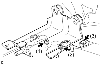
  1. Install the brake actuator bracket assembly with the 3 bolts.

    Torque:
    19 N*m{ 194 kgf*cm , 14 ft.*lbf }

    NOTICE:
    1. Do not kink or damage the brake lines.
    2. Tighten the 3 bolts in the order in the illustration.

  1. Engage the 2 clamps to install the frame wire to the brake actuator bracket assembly.


2. INSTALL ENGINE UNDER COVER LH


3. INSTALL FRONT WHEEL LH

Torque:
103 N*m{ 1050 kgf*cm , 76 ft.*lbf }


4. INSTALL BRAKE BOOSTER PUMP ASSEMBLY


    C256176E01
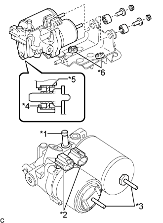
  1. Install the brake booster pump assembly to the brake actuator bracket assembly with the 2 brake booster pump bushings, 2 brake actuator case collars and 2 nuts.
    Text in Illustration 
    *1
    Union
    *2
    Connector
    *3
    Stud
    *4
    Brake Booster Pump Collar
    *5
    Brake Booster Pump Bushing
    *6
    Brake Actuator Bracket Cushion

    Torque:
    5.4 N*m{ 55 kgf*cm , 48 in.*lbf }

    NOTICE:
    1. Do not carry the brake booster pump assembly by the parts shown in bold (*1, *2 and *3) in the illustration.
    2. Do not drop the brake booster pump assembly when carrying it. If the brake booster pump assembly has been dropped, replace it with a new one.
    3. Do not kink or damage the brake lines. If they are damaged, replace them with new ones.
    4. Be careful not to allow any brake fluid to enter the connector.
    5. When installing the brake booster pump assembly to the brake actuator bracket assembly, confirm that the brake booster pump collar*4 and brake booster pump bushing*5 are installed on the brake booster pump assembly, and 2 brake actuator bracket cushions*6 are installed on the brake actuator bracket assembly.
    6. If installing a new brake booster pump assembly, do not remove the hole plug before connecting the brake lines because the brake booster pump assembly is filled with brake fluid.

  1. Connect the 2 connectors to the brake booster pump assembly.


5. INSTALL NO. 1 BRAKE TUBE CLAMP BRACKET
  1. Install the No. 1 brake tube clamp bracket to the brake booster pump assembly with the bolt.

    Torque:
    7.0 N*m{ 71 kgf*cm , 62 in.*lbf }


6. INSTALL FRONT NO. 1 BRAKE TUBE
  1. Temporarily tighten the union nut of the front No. 1 brake tube to the brake booster pump assembly.

  1. Install the bolt to secure the front No. 1 brake tube to the No. 1 brake tube clamp bracket.

    Torque:
    7.0 N*m{ 71 kgf*cm , 62 in.*lbf }

  1. Using a union nut wrench, fully tighten the front No. 1 brake tube.

    Torque:
    15 N*m{ 155 kgf*cm , 11 ft.*lbf }

    NOTICE:
    Use the formula to calculate special torque values for situations where the union nut wrench is combined with a torque wrench (Click here).


7. INSTALL BRAKE ACTUATOR HOSE


    C274355E01
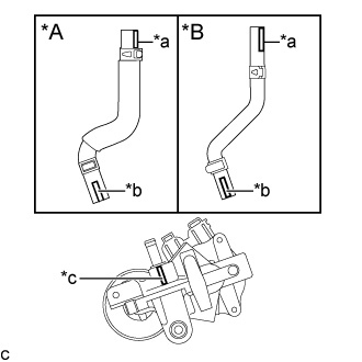
  1. Connect the brake actuator hose to the brake booster pump assembly.
    Text in Illustration 
    *A
    for Type A
    *B
    for Type B
    *a
    Identification Mark (Red)
    *b
    Identification Mark (Yellowish Green)
    *c
    Rib (Unpainted)

    NOTICE:
    1. Make sure that the identification mark (yellowish green) on the brake actuator hose is positioned within 30° of the brake booster pump rib.
    2. Make sure to install the hose to the proper location.


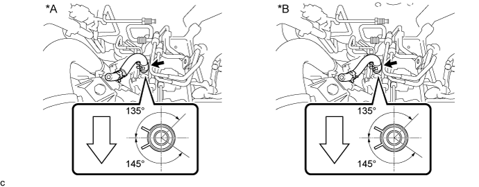
  1. Move the clip to secure the brake actuator hose.

    C274356E01


    Text in Illustration 
    *A
    for Type A
    *B
    for Type B
    V100136
    Front of Vehicle
    -
    -

    NOTICE:
    Install the clip within the range shown in the illustration.


8. INSTALL BRAKE BOOSTER WITH MASTER CYLINDER ASSEMBLY
(Click here)