 |
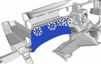
Engage the 3 claws and guide.
LOWER INSTRUMENT PANEL > REASSEMBLY |
| 1. INSTALL NO. 1 INSTRUMENT CLUSTER FINISH PANEL SEAL |
|
Engage the 3 claws and guide.
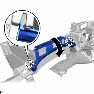 |
Engage the 2 claws as shown in the illustration.
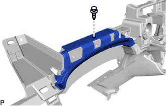 |
Install the No. 1 instrument cluster finish panel seal with the clip.
| 2. INSTALL SPARE SWITCH HOLE COVER (for RHD) |
Engage the 2 claws to install the spare switch hole cover.
| 3. INSTALL POWER SWITCH (for LHD) |
Connect the power switch connector.
Engage the 2 claws to install the power switch.
| 4. INSTALL NO. 1 POWER OUTLET SOCKET COVER |
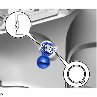 |
Align the protrusion of the No. 1 power outlet socket cover with the cutout of the lower instrument panel.
Engage the 2 claws and install the No. 1 power outlet socket cover.
| 5. INSTALL NO. 1 POWER OUTLET SOCKET ASSEMBLY |
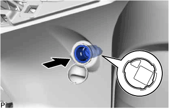 |
Align the protrusion of the No. 1 power outlet socket assembly with the cutout of the No. 1 power outlet socket cover and install the No. 1 power outlet socket.
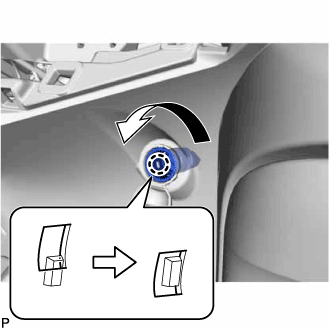 |
Turn the No. 1 power outlet socket assembly counterclockwise and securely engage the claw.
Connect the connector.
| 6. INSTALL GLOVE COMPARTMENT DOOR STOPPER SUB-ASSEMBLY |
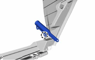 |
Engage the claw to install the glove compartment door stopper sub-assembly.