Home › Engine / Hybrid System › 1NZ-FXE ENGINE MECHANICAL › ENGINE UNIT

ENGINE UNIT > INSTALLATION

for Preparation Click here


1. INSTALL IGNITION COIL ASSEMBLY


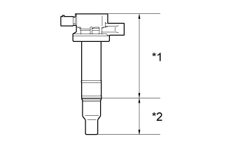
    A268161E01
  1. Install the 4 No. 1 ignition coils with the 4 bolts.
    Text in Illustration 
    *a
    Body
    *b
    Cap

    Torque:
    10 N*m{ 102 kgf*cm , 7 ft.*lbf }

    NOTICE:
    If the body or cap of the No. 1 ignition coil is dropped or subjected to a strong impact, replace the No. 1 ignition coil with a new one.

    HINT:
    Perform "Inspection After Repairs" after replacing the ignition coil assembly (Click here).
  1. Connect the 4 No. 1 ignition coil connectors.


2. INSTALL ENGINE OIL LEVEL DIPSTICK
  1. Install the engine oil level dipstick.


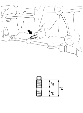
3. INSTALL STUD BOLT


    A275767E01
  1. Using an E7 "TORX" socket wrench, install the stud bolt.
    Text in Illustration 
    *a
    18.0 mm (0.709 in.)
    *b
    13.0 mm (0.512 in.)
    *c
    33.0 mm (1.30 in.)

    Torque:
    9.0 N*m{ 92 kgf*cm , 80 in.*lbf }


4. INSTALL WIRE HARNESS CLAMP BRACKET (for LHD)
  1. Install the wire harness clamp bracket with the bolt.

    Torque:
    8.4 N*m{ 85 kgf*cm , 74 in.*lbf }


5. INSTALL NO. 1 WATER BY-PASS PIPE
  1. Install the No. 1 water by-pass pipe with the 3 bolts.

    Torque:
    10 N*m{ 102 kgf*cm , 7 ft.*lbf }

  1. Connect the water hose.


6. INSTALL NO. 4 WATER BY-PASS HOSE
  1. Install the No. 4 water by-pass hose with the bolt.

    Torque:
    10 N*m{ 102 kgf*cm , 7 ft.*lbf }

  1. Connect the No. 4 water by-pass hose.


7. INSTALL EXHAUST MANIFOLD
  1. Set a new gasket to the cylinder head sub-assembly.

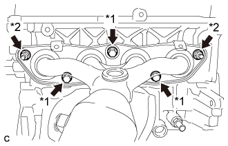
  1. Temporarily install the exhaust manifold with the 3 bolts and 2 nuts.

  1. Temporarily install the manifold support bracket with the 3 bolts.


    A267694E01
  1. Tighten the exhaust manifold with the 3 bolts and 2 nuts.
    Text in Illustration 
    *1
    Bolt
    *2
    Nut

    Torque:
    30 N*m{ 306 kgf*cm , 22 ft.*lbf }

  1. Connect the wire harness clamp and heated oxygen sensor connector.

  1. Remove the 3 bolts and manifold support bracket.


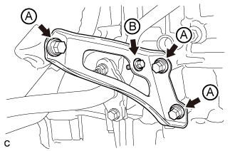
8. INSTALL MANIFOLD SUPPORT BRACKET


    A267692E01
  1. Install the manifold support bracket with the 4 bolts.

    Torque:
    Bolt A:
    44 N*m{ 449 kgf*cm , 32 ft.*lbf }
    Bolt B:
    10 N*m{ 102 kgf*cm , 7 ft.*lbf }


9. INSTALL NO. 1 EXHAUST MANIFOLD HEAT INSULATOR
  1. Install the No. 1 exhaust manifold heat insulator with the 3 bolts.

    Torque:
    8.0 N*m{ 82 kgf*cm , 71 in.*lbf }


10. INSTALL INTAKE MANIFOLD
  1. Install a new No. 1 intake manifold to head gasket to the intake manifold.

  1. Install the intake manifold insulator with the bolt.

    Torque:
    10 N*m{ 102 kgf*cm , 7 ft.*lbf }

  1. Connect the ventilation hose.

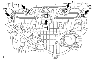
  1. Temporarily install the intake manifold and intake manifold stay with the 5 bolts and 2 nuts.


    A268526E01
  1. Tighten the intake manifold with the 3 bolts and 2 nuts.
    Text in Illustration 
    *1
    Bolt
    *2
    Nut

    Torque:
    21 N*m{ 214 kgf*cm , 15 ft.*lbf }

  1. Connect the fuel vapor feed hose and ventilation hose.


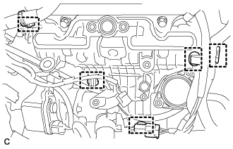
    A267685
  1. Connect the 4 wire harness clamps and water by-pass hose.


11. INSTALL INTAKE MANIFOLD STAY
  1. Tighten the intake manifold stay with the 2 bolts.

    Torque:
    10 N*m{ 102 kgf*cm , 7 ft.*lbf }


12. INSTALL EGR VALVE WITH COOLER ASSEMBLY
  1. Using an E8 "TORX" socket wrench, install the 2 stud bolts.

    Torque:
    9.0 N*m{ 92 kgf*cm , 80 in.*lbf }

  1. Install a new gasket and the EGR valve assembly with the 2 bolts.

    Torque:
    25 N*m{ 255 kgf*cm , 18 ft.*lbf }

  1. Connect the No. 1 water by-pass hose.

  1. Temporarily install a new gasket and the EGR valve with cooler assembly with the 2 bolts and 2 nuts.

  1. Install the EGR valve bracket with the 2 bolts and nut.

    Torque:
    25 N*m{ 255 kgf*cm , 18 ft.*lbf }

  1. Install the EGR valve with cooler assembly with the 2 bolts and 2 nuts.

    Torque:
    25 N*m{ 255 kgf*cm , 18 ft.*lbf }

    NOTICE:
    Make sure that all installation surfaces of the EGR valve with cooler assembly are in even contact when tightening the bolts and nuts.


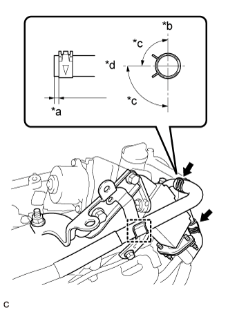
    A275468E01
  1. Connect the No. 4 water by-pass hose and No. 5 water by-pass hose.
    Text in Illustration 
    *a
    2 to 7 mm (0.079 to 0.276 in.)
    *b
    Up
    *c
    90°
    *d
    Engine Rear

  1. Install the wire harness clamp bracket with the bolt.

    Torque:
    13 N*m{ 127 kgf*cm , 9 ft.*lbf }


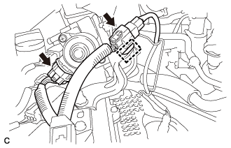
    A267673
  1. Connect the 2 connectors and wire harness clamp.


13. INSTALL NO. 2 EGR PIPE


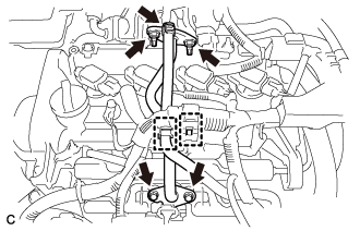
    A268229
  1. Install 2 new gaskets and the No. 2 EGR pipe with the 2 bolts and 2 nuts.

    Torque:
    Bolt:
    10 N*m{ 102 kgf*cm , 7 ft.*lbf }
    Nut:
    25 N*m{ 255 kgf*cm , 18 ft.*lbf }

    NOTICE:
    Make sure to tighten the 4 bolts evenly until the flanges of the EGR pipe assembly contact the installation surfaces.

  1. Connect the clamp and No. 2 water by-pass hose.

  1. Connect the wire harness clamp.