VEHICLE PROXIMITY NOTIFICATION SYSTEM VEHICLE PROXIMITY NOTIFICATION SYSTEM TERMINALS OF ECU
CHECK VEHICLE APPROACHING SPEAKER CONTROLLER
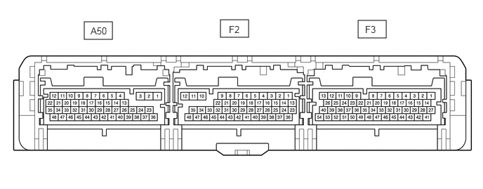
Disconnect the F2 hybrid vehicle control ECU connector.
Disconnect the F3 hybrid vehicle control ECU connector.
Measure the voltage according to the value(s) in the table below.
| Terminal No. (Symbol) | Wiring Color | Terminal Description | Condition | Specified Condition |
|---|---|---|---|---|
| F2-35(IG2) ←→ Body ground | BE - Body ground | IG power supply | Power switch off | Below 1 V |
| Power switch on (IG) | 11 to 14 V | |||
| F3-27(BATT) ←→ Body ground | GR - Body ground | Auxiliary battery power supply | Power switch off | 11 to 14 V |
If the result is not as specified, there may be a malfunction in the wire harness.
Measure the resistance according to the value(s) in the table below.
| Terminal No. (Symbol) | Wiring Color | Terminal Description | Condition | Specified Condition |
|---|---|---|---|---|
| F2-10(E03) ←→ Body ground | W-B - Body ground | Ground | Always | Below 1 Ω |
| F2-11(E02) ←→ Body ground | W-B - Body ground | Ground | Always | Below 1 Ω |
| F2-12(E01) ←→ Body ground | W-B - Body ground | Ground | Always | Below 1 Ω |
If the result is not as specified, there may be a malfunction in the wire harness.
Reconnect the F2 hybrid vehicle control ECU connector.
Reconnect the F3 hybrid vehicle control ECU connector.
Measure the voltage and check for pulses according to the value(s) in the table below.
| Terminal No. (Symbol) | Wiring Color | Terminal Description | Condition | Specified Condition |
|---|---|---|---|---|
| A50-19 (SPK+) - A50-9 (SPK-) | B - V | Vehicle approaching speaker output | Vehicle approaching speaker operating | A waveform synchronized with the sound is output.
(See Waveform 1) |
| F3-9 (KIND) - Body ground | L - Body ground | Vehicle approaching speaker switch indicator signal output | Power switch on (IG), pattern select switch assembly (vehicle approaching speaker switch) off | Below 1.8 V |
| Power switch on (IG), pattern select switch assembly (vehicle approaching speaker switch) ON | 11 to 14 V | |||
| F3-22 (SW) - Body ground | G - Body ground | Vehicle approaching speaker switch signal input | Power switch on (IG), pattern select switch assembly (vehicle approaching speaker switch) off | Below 1 V |
| Power switch on (IG), pattern select switch assembly (vehicle approaching speaker switch) ON | 11 to 14 V |
If the result is not as specified, there is a problem in the hybrid vehicle control ECU or wire harness.
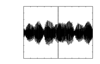
Waveform 1
| Item | Condition |
|---|---|
| Tool setting | 1 V/DIV., 200 ms./DIV. |
| Vehicle condition | Vehicle approaching speaker operating |