RM3210E
_56
Audio / Visual / Telematics
_047510
AUDIO / VIDEO
_0243397
AUDIO AND VISUAL SYSTEM
J
AUDIO / VIDEO AUDIO AND VISUAL SYSTEM Sound Signal Circuit between Radio Receiver and Stereo Jack Adapter
DESCRIPTION
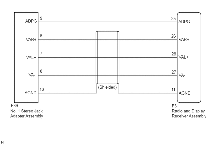
The No. 1 stereo jack adapter assembly sends the sound signal from an external device to the radio and display receiver assembly via this circuit.
The sound signal that is sent is amplified by the radio and display receiver assembly and then is sent to the speakers.
If there is an open or short in this circuit, sound cannot be heard from the speakers even if the radio and display receiver assembly or speakers are not malfunctioning.
WIRING DIAGRAM
0.844,0.615 1.458,0.813
0.615,0.198
10
false
ADPG
0.875,1.823 1.49,2.021
0.615,0.198
10
false
VAL+
0.958,2.406 1.573,2.604
0.615,0.198
10
false
VA-
0.823,3 1.438,3.198
0.615,0.198
10
false
AGND
0.865,1.229 1.479,1.427
0.615,0.198
10
false
VAR+
1.333,0.521 1.948,0.719
0.615,0.198
10
false
9
1.333,1.104 1.948,1.302
0.615,0.198
10
false
6
1.333,1.698 1.948,1.896
0.615,0.198
10
false
7
1.333,2.281 1.948,2.479
0.615,0.198
10
false
8
1.313,2.885 1.927,3.083
0.615,0.198
10
false
10
3.271,2.813 3.948,3.01
0.677,0.198
10
false
(Shielded)
5.948,0.635 6.563,0.833
0.615,0.198
10
false
ADPG
5.958,1.229 6.573,1.427
0.615,0.198
10
false
VAR+
5.958,1.813 6.573,2.01
0.615,0.198
10
false
VAL+
5.958,2.417 6.573,2.615
0.615,0.198
10
false
VA-
5.958,3.01 6.573,3.208
0.615,0.198
10
false
AGND
5.708,0.531 6.323,0.729
0.615,0.198
10
false
25
5.708,1.115 6.323,1.313
0.615,0.198
10
false
26
5.719,1.708 6.333,1.906
0.615,0.198
10
false
28
5.719,2.313 6.333,2.51
0.615,0.198
10
false
27
5.708,2.896 6.323,3.094
0.615,0.198
10
false
11
0.365,3.427 0.979,3.625
0.615,0.198
10
false
F39
0.344,3.604 1.5,4.167
1.156,0.563
10
false
No. 1 Stereo Jack Adapter Assembly
5.729,3.438 6.344,3.635
0.615,0.198
10
false
F31
5.729,3.604 6.948,4.156
1.219,0.552
10
false
Radio and Display Receiver Assembly
PROCEDURE
1.CHECK HARNESS AND CONNECTOR (RADIO AND DISPLAY RECEIVER ASSEMBLY - NO. 1 STEREO JACK ADAPTER ASSEMBLY)
a.
Disconnect the F31 radio and display receiver assembly connector.
b.
Disconnect the F39 No. 1 stereo jack adapter assembly connector.
c.
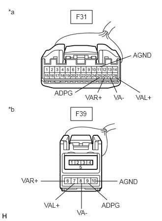
1.5,0.219 1.958,0.5
0.458,0.281
1.5,2.271 1.958,2.552
0.458,0.281
2.115,1.417 2.781,1.177
false
2.219,1.635 2.073,1.958
false
2.115,1.635 1.594,1.958
false
2.448,1.635 2.969,1.958
false
2.333,1.635 2.479,1.958
false
1.583,3.875 1.177,4.229
false
1.875,3.875 2.271,4.229
false
2.042,3.833 2.49,3.833
false
1.385,3.833 0.865,3.833
false
1.729,3.875 1.729,4.417
false
2.823,1.083 3.25,1.229
0.427,0.146
10
false
AGND
1.813,1.979 2.323,2.365
0.51,0.385
10
false
VAR+
1.156,1.885 1.719,2.167
0.563,0.281
10
false
ADPG
2.885,1.979 3.25,2.125
0.365,0.146
10
false
VAL+
2.417,1.979 2.667,2.125
0.25,0.146
10
false
VA-
0.177,0.167 0.604,0.771
0.427,0.604
10
false
*a
1.615,0.271 2.083,0.521
0.469,0.25
10
false
F31
2.531,3.76 2.958,3.906
0.427,0.146
10
false
AGND
0.938,4.26 1.344,4.531
0.406,0.271
10
false
VAL+
2.156,4.26 2.667,4.479
0.51,0.219
10
false
ADPG
0.177,2.229 0.563,2.542
0.385,0.313
10
false
*b
0.458,3.74 0.917,4.052
0.458,0.313
10
false
VAR+
1.635,4.417 2.083,4.594
0.448,0.177
10
false
VA-
1.604,2.323 2.104,2.583
0.5,0.26
10
false
F39
| *a | Front view of wire harness connector
(to Radio and Display Receiver Assembly) |
| *b | Front view of wire harness connector
(to No. 1 Stereo Jack Adapter Assembly) |
Measure the resistance according to the value(s) in the table below.
- Standard Resistance:
Tester Connection Condition Specified Condition F31-25 (ADPG) - F39-9 (ADPG) Always Below 1 Ω F31-11 (AGND) - F39-10 (AGND) Always Below 1 Ω F31-26 (VAR+) - F39-6 (VAR+) Always Below 1 Ω F31-28 (VAL+) - F39-7 (VAL+) Always Below 1 Ω F31-27 (VA-) - F39-8 (VA-) Always Below 1 Ω F31-25 (ADPG) or F39-9 (ADPG) - Body ground Always 10 kΩ or higher F31-11 (AGND) or F39-10 (AGND) - Body ground Always 10 kΩ or higher F31-26 (VAR+) or F39-6 (VAR+) - Body ground Always 10 kΩ or higher F31-28 (VAL+) or F39-7 (VAL+) - Body ground Always 10 kΩ or higher F31-27 (VA-) or F39-8 (VA-) - Body ground Always 10 kΩ or higher
- Result:
Proceed to OK NG
OK
PROCEED TO NEXT SUSPECTED AREA SHOWN IN PROBLEM SYMPTOMS TABLE
NG
REPAIR OR REPLACE HARNESS OR CONNECTOR