INSTALLATION
Removal / installation · Vehicles built Nov 2005 – Dec 2006
Versions by build date: Nov 2005 – Dec 2006 Jan 2007 – Jul 2007 from Aug 2007
| 1. INSTALL FUEL TANK ASSEMBLY |

  |
Set the fuel tank on a mission jack.
Lift up the mission jack.
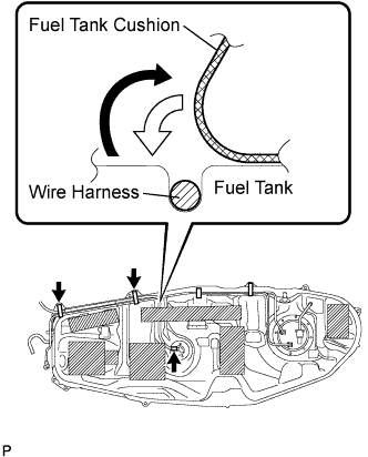
Fold back the 2 cushion rubbers.
Connect the sender gauge connector to the fuel tank.
- NOTICE:
- Be careful not to cut the wirings.
Attach the wire harness to the 2 clamps.
Install the 3 fuel tank bands with the 6 bolts.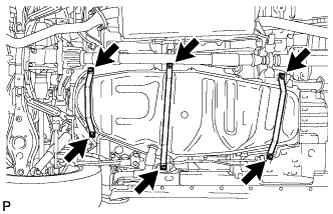
- Torque:
- 40 N*m{ 408 kgf*cm , 30 ft.*lbf }
| 2. INSTALL FUEL TANK FILLER PIPE |
Install the filler pipe with the 2 bolts.
- Torque:
- 23.5 N*m{ 240 kgf*cm , 17 ft.*lbf }
Install the filler pipe protector with the 3 bolts.
- Torque:
- 5.4 N*m{ 55 kgf*cm , 48 in.*lbf }
| 3. CONNECT FUEL TANK TO FILLER PIPE HOSE |
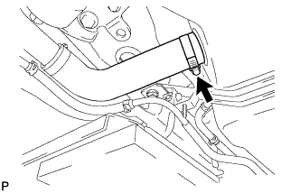 |
Connect the filler pipe hose to the fuel tank.
| 4. CONNECT FUEL TANK BREATHER HOSE |
Connect the fuel tank breather hose to the fuel tank.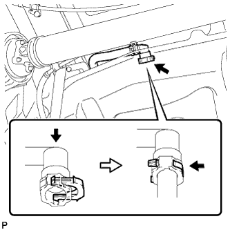
- NOTICE:
- Before installing the pipe, make sure that it is not damaged. Make sure that there are no dirt present on the connecting surfaces.
- Before installing the pipe, make sure that it is not damaged. Make sure that there are no dirt present on the connecting surfaces.
- After connecting, check if the pipe and the connector are securely connected by pulling on them.
- After connecting, check if the pipe and the connector are securely connected by pulling on them.
| 5. CONNECT FUEL TANK MAIN TUBE SUB-ASSEMBLY |
- NOTICE:
- Before installing the tube connectors to the pipes, check the connectors for damage and foreign matter.
Connect the main tube connector to the pipe. Push the 2 parts together firmly until a "click" sound is heard.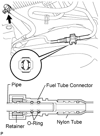
- NOTICE:
- Check that the connectors and pipes are securely connected by trying to pull them apart.
Connect the fuel tank return tube.
| 6. INSTALL NO. 1 FUEL TANK PROTECTOR |
Install the fuel tank protector with the 3 clips and 2 bolts.
- Torque:
- 20 N*m{ 204 kgf*cm , 15 ft.*lbf }
| 7. INSTALL NO. 1 FLOOR UNDER COVER |
Install the floor under cover with the clip and 2 nuts.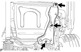
| 8. INSTALL FRONT FLOOR COVER |
Install the floor cover with the 3 clips, bolt, nut.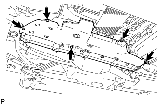
| 9. CONNECT NO. 2 PARKING BRAKE CABLE ASSEMBLY |
Connect the parking brake cable with the 2 bolts.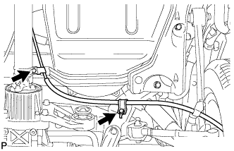
| 10. INSTALL FUEL TANK CAP |
| 11. CONNECT CABLE TO NEGATIVE BATTERY TERMINAL |
| 12. BLEED AIR FROM FUEL SYSTEM |
Using the hand pump, bleed air from the fuel system until pumping becomes difficult.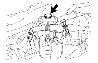
| 13. CHECK FOR FUEL LEAKS |
PERFORM ACTIVE TEST
Connect the intelligent tester to the DLC3.
Start the engine.
Turn the intelligent tester ON.
Enter the following menus: Powertrain / Engine / Active Test.
Perform the Active Test.
Intelligent Tester Display
Test Details
Control Range
Diagnostic Notes
Test the Fuel Leak
Pressurizing common rail internal fuel pressure, and checking for fuel leaks
Stop/Start
- Fuel pressure inside common rail pressurized to specified value and engine speed increased to 2,000 rpm when start is selected
- Above conditions to be maintained while test is started
- Fuel pressure inside common rail pressurized to specified value and engine speed increased to 2,000 rpm when start is selected