TERMINALS OF ECU
System information · Vehicles built Nov 2005 – Jul 2008
Versions by build date: Nov 2005 – Jul 2008 from Aug 2008
| CHECK RADIO RECEIVER ASSEMBLY |
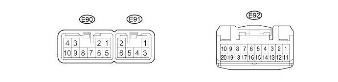

Disconnect the E90 receiver connector.
Measure the resistance and voltage of the wire harness side connector.
If the results are not as specified, there may be a malfunction on the wire harness side.Symbols (Terminal No.)
Wiring Color
Terminal Description
Condition
Specified Condition
GND (E90-7) - Body ground
BR - Body ground
Ground
Always
Below 1 Ω
ACC (E90-3) - Body ground
GR - Body ground
ACC power supply
Ignition switch on (ACC)
10 to 14 V
B (E90-4) - Body ground
L - Body ground
Battery power supply
Always
10 to 14 V
ILL+ (E90-10) - Body ground
G - Body ground
Illumination signal
Light control switch TAIL
10 to 14 V
Reconnect the E90 receiver connector.
Measure the voltage of the connectors.
Symbols (Terminal No.)
Wiring Color
Terminal Description
Condition
Specified Condition
RR+ (E91-1) - GND (E90-7)
R - BR
Sounds signal (rear right)
Audio system is operating
Waveform synchronized with sound is output
RL+ (E91-2) - GND (E90-7)
B - BR
Sounds signal (rear left)
Audio system is operating
Waveform synchronized with sound is output
RR- (E91-3) - GND (E90-7)
W - BR
Sounds signal (rear right)
Audio system is operating
Waveform synchronized with sound is output
RL- (E91-6) - GND (E90-7)
Y - BR
Sounds signal (rear left)
Audio system is operating
Waveform synchronized with sound is output
FR+ (E90-1) - GND (E90-7)
LG - BR
Sounds signal (front right)
Audio system is operating
Waveform synchronized with sound is output
FL+ (E90-2) - GND (E90-7)
P - BR
Sounds signal (front left)
Audio system is operating
Waveform synchronized with sound is output
FR- (E90-5) - GND (E90-7)
L - BR
Sounds signal (front right)
Audio system is operating
Waveform synchronized with sound is output
FL- (E90-6) - GND (E90-7)
V - BR
Sounds signal (front left)
Audio system is operating
Waveform synchronized with sound is output
ANT (E90-8) - GND (E90-7)
O - BR
Power source of antenna
Radio switch ON and set to AM or FM
10 to 14 V
SW1 (E92-7) - SWG (E92-6)*
W - B
Steering pad switch signal
Steering pad switch not pushed
4 V or more
SW1 (E92-7) - SWG (E92-6)*
W - B
Steering pad switch signal
Steering pad switch
SEEK+ switch pushed
Approx. 0.1 V
SW1 (E92-7) - SWG (E92-6)*
W - B
Steering pad switch signal
Steering pad switch
SEEK- switch pushed
Approx. 0.9 V
SW1 (E92-7) - SWG (E92-6)*
W - B
Steering pad switch signal
Steering pad switch
VOL+ switch pushed
Approx. 1.5 V
SW1 (E92-7) - SWG (E92-6)*
W - B
Steering pad switch signal
Steering pad switch
VOL- switch pushed
Approx. 3 V
SW2 (E92-8) - SWG (E92-6)*
R - B
Steering pad switch signal
Steering pad switch
not pushed
4 V or more
SW2 (E92-8) - SWG (E92-6)*
R - B
Steering pad switch signal
Steering pad switch
MODE switch pushed
Below 0.1 V
- HINT:
- *: w/ Steering Pad Switch