REMOVAL
Removal / installation · Vehicles built from Jan 2007
Versions by build date: Nov 2005 – Dec 2006 from Jan 2007
| 1.
DISCONNECT CABLE FROM NEGATIVE BATTERY TERMINAL |
 |
- CAUTION:
- Wait at least 90 seconds after disconnecting the cable from the negative (-) battery terminal to prevent airbag and seat belt pretensioner activation.
| 2.
PLACE FRONT WHEELS FACING STRAIGHT AHEAD |
|
| 3.
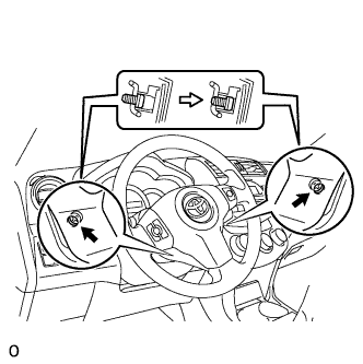
REMOVE STEERING PAD ASSEMBLY
|
|
Straighten the front wheels.
Using a T30 "torx" driver, loosen the 2 screws until the groove along each screw circumference catches on the screw case.
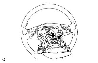
- Pull out the steering pad from the steering wheel and support the steering pad with one hand as shown in the illustration.
- NOTICE:
- When removing the steering pad, do not pull the airbag wire harness.
Using a screwdriver, disconnect the 2 airbag connectors.
- CAUTION:
- When handling the airbag connector, do not damage the airbag wire harness.
Disconnect the horn connector and remove the steering pad.
| 4.
REMOVE STEERING WHEEL ASSEMBLY
|
|
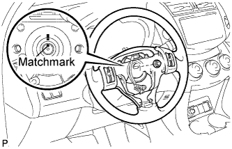
- Remove the nut and place matchmarks on the steering wheel and steering column.
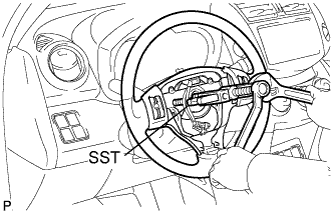
- Using SST, remove the steering wheel.
- SST
- 09950-50013
(09951-05010, 09952-05010, 09953-05020, 09954-05021)
- NOTICE:
- Apply a small amount of grease to the threads and tip of SST (center bolt) before use.
| 5.
REMOVE STEERING COLUMN COVER
|
|
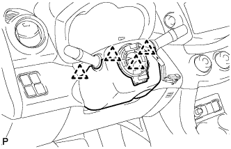
- Detatch the 4 claws, release the tilt lever and remove the lower steering column cover.
- Detach the claw and remove the upper steering column cover.
| 6.
REMOVE SPIRAL CABLE SUB-ASSEMBLY
|
|
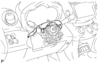
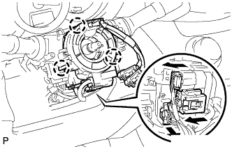
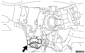
- Disconnect all connectors from the turn signal switch with spiral cable.
| 7.
REMOVE WIPER AND WASHER SWITCH ASSEMBLY
|
|
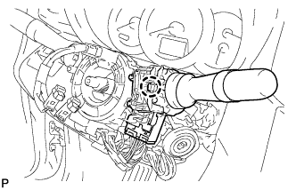
Disconnect the connectors.
Detach the claw and remove the wiper switch.
- NOTICE:
- Do not push the claw with excessive force as damage may occur.
| 8.
REMOVE HEADLIGHT DIMMER SWITCH ASSEMBLY |
|
- Disconnect the connector.
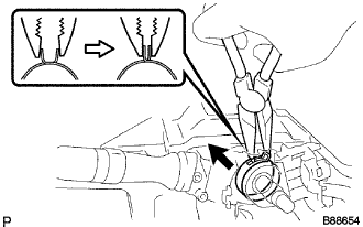
- Using needle-nose pliers, remove the band clamp as shown in the illustration.
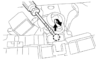
- Using a screwdriver, detach the claws and remove the switch.
- HINT:
- Tape the screwdriver tip before use.