Removal / installation · Vehicles built from Nov 2005
1.
DISCONNECT CABLE FROM NEGATIVE BATTERY TERMINAL
CAUTION:
Wait at least 90 seconds after disconnecting the cable from the negative (-) battery terminal to prevent airbag and seat belt pretensioner activation.
2.
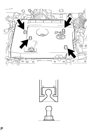
REMOVE NO. 1 ENGINE COVER
Detach the 4 clips and remove the engine cover.
3.
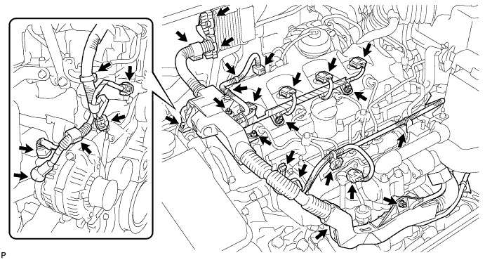
DISCONNECT ENGINE WIRE
Remove the nut and disconnect the 3 sensor connectors, 2 clamps and generator wire.
Disconnect the 2 injector driver connectors and clamp.
Disconnect the vacuum regulating valve connector and 2 clamps.
Disconnect the 4 injector connectors and 2 nuts.
Remove the grommet and nut and disconnect the glow plug wire harness.
Disconnect the common rail connector.
Disconnect the pressure sensor connector and 2 clamps.
Remove the bolt, 2 nuts and disconnect the engine wire from the engine cover bracket.
Remove the nut and disconnect the engine wire from the wire bracket.
4.
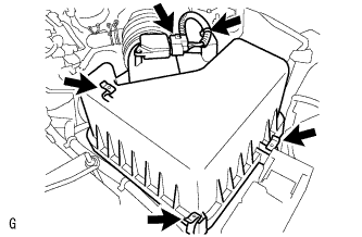
REMOVE AIR CLEANER CAP SUB-ASSEMBLY
Disconnect the mass air flow meter connector.
Disconnect the wire harness clamp.
Unhook the 3 hook clamps, and then remove the air cleaner cap.
Remove the air cleaner filter element from the air cleaner case.
5.
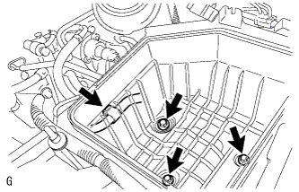
REMOVE AIR CLEANER ASSEMBLY WITH ELEMENT
Disconnect the wire harness clamp and remove the 3 bolts and air cleaner case.
6.
REMOVE FUEL INLET PIPE SUB-ASSEMBLY
NOTICE:
After removing the fuel inlet pipe, cover the common rail and injection pump with electrical tape to prevent dust from entering them.
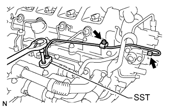
Remove the nut and 2 fuel inlet pipe clamps.
Using SST, remove the fuel inlet pipe.
SST
09023-38401
7.
REMOVE INJECTION PIPE SUB-ASSEMBLY
NOTICE:
After removing the injection pipe, to prevent dirt or foreign from entering the pipe inlet, cover the common rail with electrical tape. Also protect the injector inlets with electrical tape or plastic bags.
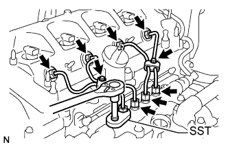
Remove the 2 bolts and 4 injection pipe clamps.
Using SST, loosen the 4 nuts at the common rail end of the injection pipe.
SST
09023-38401
Using SST, loosen the 4 nuts at the injector end of the injection pipe.
SST
09023-12701
Remove the 4 injection pipes.
8.
REMOVE NO. 2 NOZZLE LEAKAGE PIPE
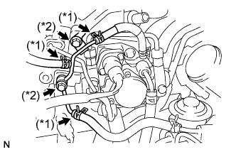
Using pliers, grip the claws of the 3 clips and slide the 3 clips to disconnect the 3 fuel hoses (*1).
Remove the 2 bolts, gasket and No. 2 nozzle leakage pipe (*2).
9.
REMOVE NOZZLE HOLDER SEAL
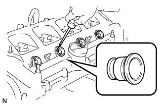
Using a screwdriver, pry out the 4 nozzle holder seals.
10.
REMOVE CYLINDER HEAD COVER SUB-ASSEMBLY
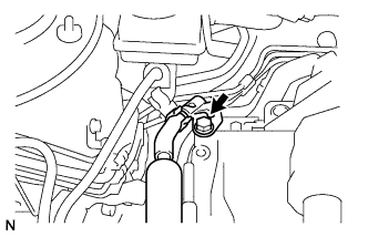
Remove the bolt.
Disconnect the power steering hose from the vacuum pump.
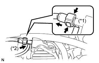
Pinch the vacuum hose connector and disconnect the vacuum hose (*1).
Disconnect the vacuum hose from the vacuum pump (*2).
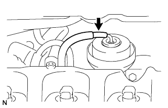
Disconnect the vacuum hose from the turbocharger actuator.
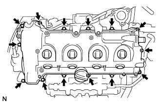
Remove the 2 nuts, 2 washers, 12 bolts, cylinder head cover and gasket.
11.
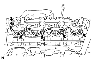
REMOVE NO. 1 NOZZLE LEAKAGE PIPE ASSEMBLY
Remove the 5 union bolts, nozzle leakage pipe and 5 gaskets.
NOTICE:
When removing the nozzle leakage pipe, place a shop rag or a piece of cloth under the pipe to protect the cylinder head from the fuel remaining inside the pipe.
12.
REMOVE NOZZLE HOLDER CLAMP NO.1
Remove the 4 bolts, 4 washers and 4 nozzle holder clamps.
13.
REMOVE INJECTOR ASSEMBLY
Remove the 4 injectors from the cylinder head.
Remove the O-rings from each injector.
Remove the 4 nozzle seats from the cylinder head.
HINT:
When replacing the injector assembly, store them in the correct order so that they can be returned to their original locations when reassembling.