2005-2008 RAV4 · Service Manual ENGINE

INSTALLATION

Removal / installation · Vehicles built from Aug 2007

Versions by build date: Nov 2005 – Dec 2006 Jan 2007 – Jul 2007 from Aug 2007


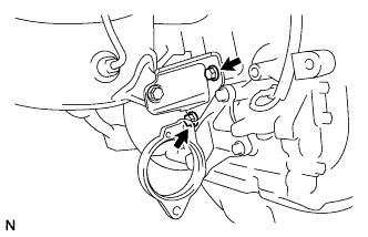
1. INSTALL NO. 2 TURBO OIL PIPE
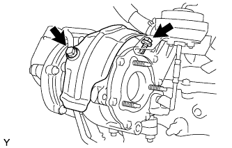
  1. Temporarily install 2 new gaskets and the turbo oil pipe with the 2 bolts.


2. INSTALL TURBOCHARGER SUB-ASSEMBLY

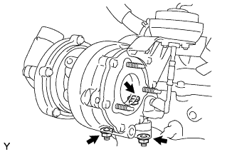
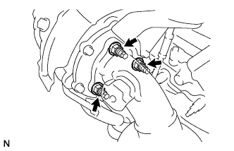
A113487
  1. Install a new gasket and the turbocharger with 3 new nuts.

    Torque:
    60 N*m{ 612 kgf*cm , 44 ft.*lbf }


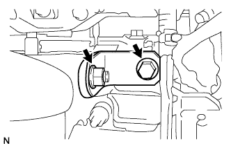
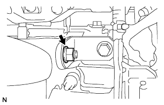
3. INSTALL TURBOCHARGER STAY

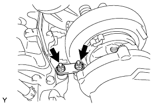
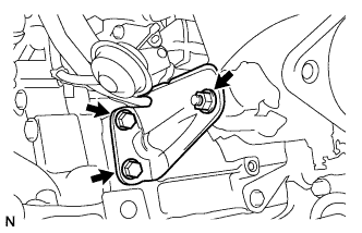
A113486
  1. Install the turbocharger stay and 2 spacers with the 2 nuts.

    Torque:
    36 N*m{ 370 kgf*cm , 26 ft.*lbf }


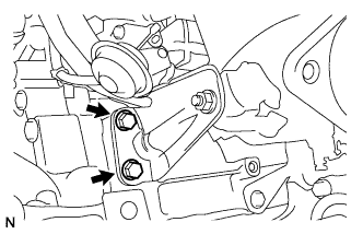
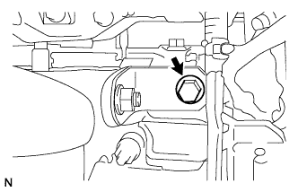
4. TIGHTEN NO. 2 TURBO OIL PIPE

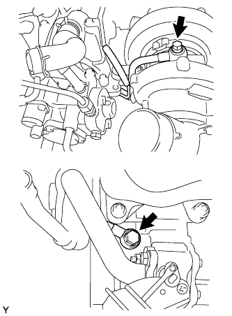
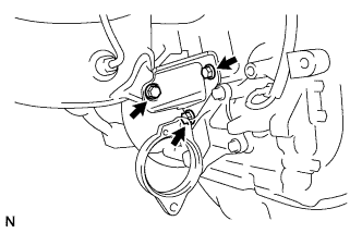
A113484
  1. Tighten the turbo oil pipe with the 2 bolts.

    Torque:
    35 N*m{ 357 kgf*cm , 26 ft.*lbf }

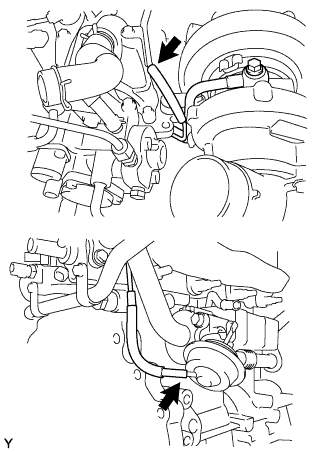
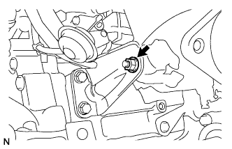
  1. A113485
    Connect the 2 vacuum hoses.


5. INSTALL TURBO OIL OUTLET PIPE

A113483
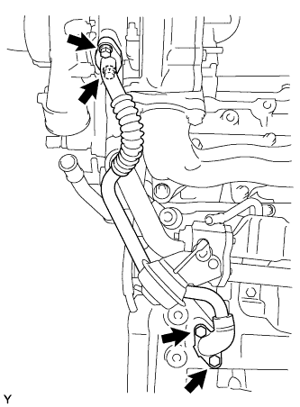
  1. Install 2 new gaskets and the oil pipe with the 4 bolts.

    Torque:
    11 N*m{ 112 kgf*cm , 8 ft.*lbf }


6. INSTALL NO. 2 TURBO WATER PIPE SUB-ASSEMBLY

  1. A113481E01
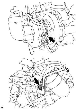
    Install a new gasket and the pipe with the 2 bolts.

    Torque:
    38 N*m{ 387 kgf*cm , 28 ft.*lbf } for bolt A
    28 N*m{ 285 kgf*cm , 21 ft.*lbf } for bolt B

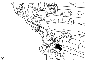
  1. Using needle-nose pliers, grip the claws of the clip and slide the clip to install the No. 3 water by-pass hose.


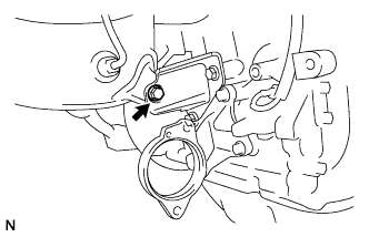
7. INSTALL NO. 1 TURBO WATER PIPE SUB-ASSEMBLY

A113482
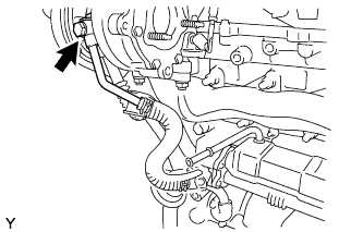
  1. Install a new gasket and the pipe with the bolt.

    Torque:
    38 N*m{ 387 kgf*cm , 28 ft.*lbf }

  1. A113480
    Using needle-nose pliers, grip the claws of the clip and slide the clip to install the No. 1 turbo water hose.


8. INSTALL NO. 1 TURBO INSULATOR

A113478
  1. Install the insulator with the 2 bolts.

    Torque:
    20.5 N*m{ 209 kgf*cm , 15 ft.*lbf }


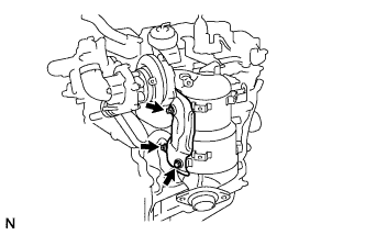
9. INSTALL EXHAUST MANIFOLD CONVERTER SUB-ASSEMBLY

  1. A110789
    Temporarily install a new turbine outlet elbow gasket and exhaust manifold converter with the 3 nuts.

  1. A110768
    Temporarily install the No. 2 exhaust manifold stay with the 2 bolts and nut.

  1. A110790
    Temporarily install the No. 2 manifold stay with the 3 bolts.

  1. A110767
    Temporarily install the No. 1 manifold stay with the bolt and nut.

  1. A116310
    Tighten the 2 bolts of the No. 2 exhaust manifold stay to the cylinder block (Upper bolt → Lower bolt).

    Torque:
    56 N*m{ 571 kgf*cm , 41 ft.*lbf }

  1. A110789
    Tighten the 3 nuts of the exhaust manifold converter to the turbocharger sub-assembly (While pushing manifold converter towards turbocharger sub-assembly).

    Torque:
    25 N*m{ 255 kgf*cm , 18 ft.*lbf }

  1. A116309
    Tighten the nut of the No. 2 exhaust manifold stay to the exhaust manifold converter.

    Torque:
    56 N*m{ 571 kgf*cm , 41 ft.*lbf }

  1. A116307
    Tighten the bolt of the No. 2 manifold stay to the exhaust manifold converter.

    Torque:
    56 N*m{ 571 kgf*cm , 41 ft.*lbf }

    HINT:
    Ensure stay pushed flush to cylinder block and manifold converter while tightening.

  1. A116308
    Tighten the 2 bolts of the No. 2 manifold stay to the cylinder block.

    Torque:
    56 N*m{ 571 kgf*cm , 41 ft.*lbf }

  1. A114989
    Tighten the bolt of the No. 1 manifold stay to the cylinder head.

    Torque:
    25 N*m{ 255 kgf*cm , 18 ft.*lbf }

    HINT:
    Ensure stay pushed flush to cylinder head and manifold converter while tightening.

  1. A114988
    Tighten the nut of the No. 1 manifold stay to the exhaust manifold converter.

    Torque:
    25 N*m{ 255 kgf*cm , 18 ft.*lbf }


10. INSTALL NO. 2 MANIFOLD CONVERTER INSULATOR

  1. A114858
    Install the No. 2 manifold converter insulator with the 3 nuts.

    Torque:
    29 N*m{ 291 kgf*cm , 21 ft.*lbf }


11. INSTALL NO. 1 MANIFOLD CONVERTER INSULATOR

  1. A114857
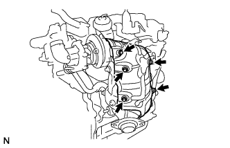
    Install the No. 1 manifold converter insulator with the 5 bolts.

    Torque:
    29 N*m{ 291 kgf*cm , 21 ft.*lbf }


12. INSTALL ENGINE ASSEMBLY
  1. Install the engine to the vehicle (Click here).


13. CONNECT CABLE TO NEGATIVE BATTERY TERMINAL
← INSTALLATION (Jan 2007 – Jul 2007)COMPONENTS (from Nov 2005) →