SYSTEM DESCRIPTION
Troubleshooting · Vehicles built from Nov 2005
| GENERAL |
The air conditioning system has the following features:
- The air conditioning amplifier controls the operation of parts, such as the A/C compressor, automatically in accordance with the operating conditions of the air conditioning system.
- The Positive Temperature Coefficient (PTC) heater system contains a PTC heater that heats the air that has passed through the heater core to ensure the proper heater performance.
- A combustion type power heater is available as optional equipment to provide comfortable heater performance in cold areas.
- The air conditioning amplifier controls the operation of parts, such as the A/C compressor, automatically in accordance with the operating conditions of the air conditioning system.
| MODE POSITION AND DAMPER OPERATION |
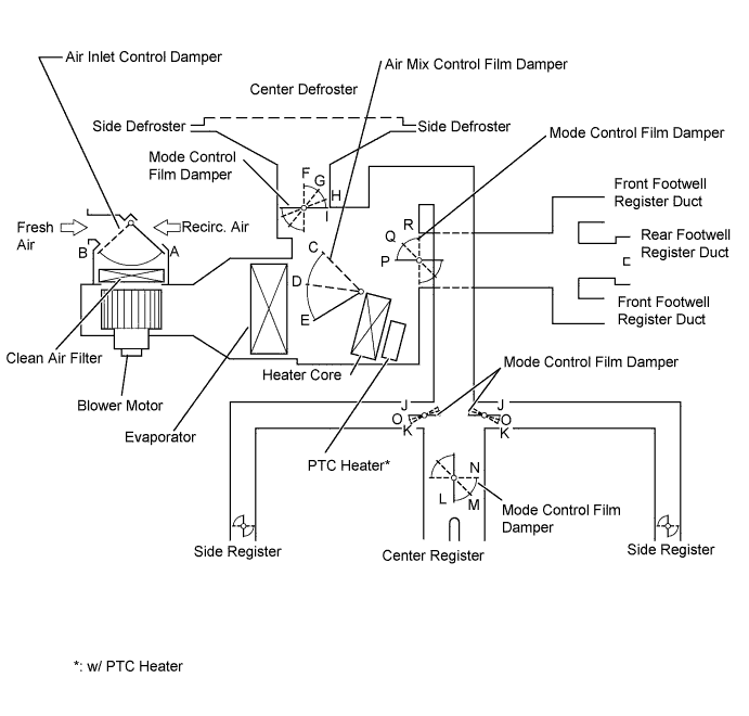

| Control Damper |
Control Position |
Damper Position |
Operation |
|
| Air Inlet Control Damper |
FRESH |
A |
Brings in fresh air. |
|
| RECIRC |
B |
Recirculates internal air. |
||
| Air Mix Control Film Damper |
COOL to HOT |
C, D, E |
Varies the mixture ratio of fresh air and the recirculation air in order to regulate the temperature continuously from HOT to COOL. |
|
| Mode Control Film Damper |
 FACE |
I, J, L, R |
Air blows out of center registers and side registers. |
|
 BI-LEVEL |
I, O, M, Q |
Air mainly blows out of center registers, side registers, and footwell register ducts. |
||
 FOOT |
H, K, N, P |
Air mainly blows out of front and rear footwell register ducts. In addition, air blows out slightly from front and side defrosters, and side registers. |
||
 FOOT/DEF |
G, K, N, Q |
Air mainly blows out of front and side defrosters to defrost windshield. Air also blows out from front and rear footwell register ducts, and side registers. |
||
 DEF |
F, K, N, R |
Air blows out of front and side defrosters and side registers to defrost windshield. |
||
| AIR OUTLET AND AIRFLOW VOLUME |
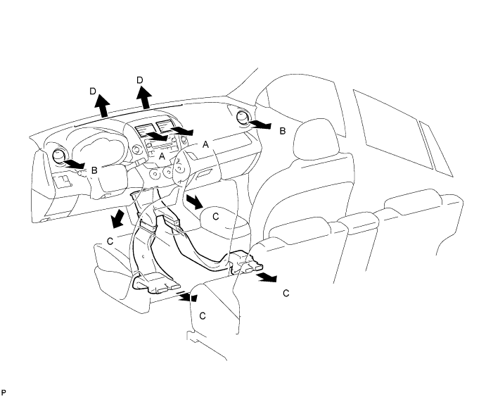
| Air Outlet Mode |
Air Outlet Position Symbol |
||||
| A |
B |
C |
D |
||
| Center Face |
Side Face |
Foot |
Defroster |
||
|
|
FACE |
 |
|
X |
X |
|
|
Bi-LEVEL |
 |
|
 |
X |
|
|
FOOT |
X |
 |
|
 |
|
|
FOOT/DEF |
X |
|
|
|
|
|
DEF |
X |
|
X |
|