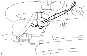
Use a sound scope to check for injector operating noise.
Check that the operating sounds stop momentarily and then resume when the throttle lever is released.
HINT:
Measure with the A/C OFF.
Fuel return rpm:
1,400 rpm
CHECK FOR LEAKS
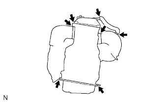
Visually check that the hoses, connections and gaskets have no cracks, leaks or damage.
NOTICE:
Detachment or other problems with the engine oil dipstick, filler cap, ventilation hose and other components may cause the engine to run improperly.
Air suction caused by disconnections, looseness or cracks in the parts of the air induction system between the throttle body and cylinder head will cause engine failure or engine malfunctions.
If the result is not as specified, replace parts as necessary.
CHECK CHARCOAL CANISTER
Inspect the ventilation of the canister.
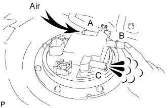
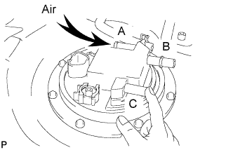
Close port B and apply compressed air into port A and check that the air flows out from port C.
HINT:
Do not wash the charcoal canister.
No activated carbon should come out.
If a problem is found, replace the fuel pump sub-assembly.
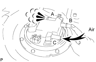
Close port B and apply compressed air into port C and check that the air flows out from port A.
HINT:
Do not wash the charcoal canister.
No activated carbon should come out.
If a problem is found, replace the fuel pump sub-assembly.
Inspect the check valve.
Close port C, and apply compressed air into port A.
Standard:
Air does not flow at first. By gradually increasing the pressure, air flows when the pressure in the port reaches the specified level.
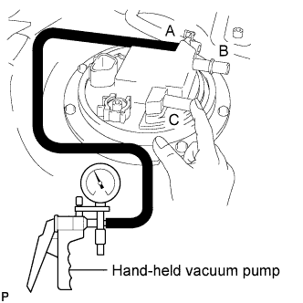
Close port C. Using a hand-held vacuum pump, apply a vacuum to port A.
Standard:
The vacuum is maintained at first. By gradually increasing the vacuum, air flows and the vacuum decreases after the vacuum reaches the specified level.