REASSEMBLY
Removal / installation · Vehicles built from Aug 2007
| 1. INSTALL FRONT DIFFERENTIAL SIDE GEAR |

Coat the 2 front differential side gears, 2 side gear thrust washers, 2 front differential pinions and 2 pinion thrust washers with ATF and install them to the differential case.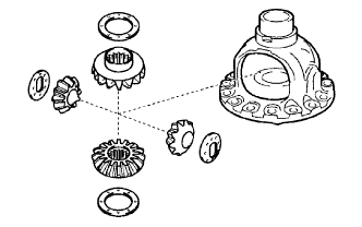

| 2. INSTALL NO. 1 FRONT DIFFERENTIAL PINION SHAFT |
Coat the No. 1 front differential pinion shaft with ATF, and install it to the differential case.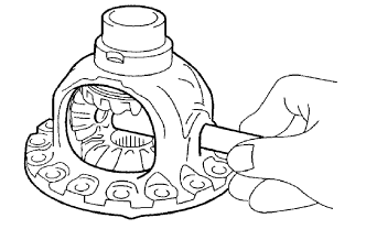
| 3. INSTALL FRONT DIFFERENTIAL PINION SHAFT STRAIGHT PIN |
Using a pin punch and a hammer, tap in the pinion shaft straight pin.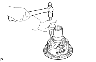
Using a chisel and a hammer, stake the differential case.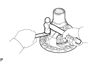
- NOTICE:
- Stake it after adjusting the backlash.
| 4. INSTALL FRONT DIFFERENTIAL CASE REAR TAPERED ROLLER BEARING |
Using SST and a press, press in the front differential case rear tapered roller bearing to the differential case.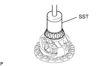
- SST
- 09550-60010
09950-60020 (09951-00680)
09950-70010 (09951-07100)
- NOTICE:
- When replacing the bearing, be sure to replace it together with the outer race.
- When replacing a bearing of the differential case, replace both the front and rear bearings together.
- When replacing the bearing, be sure to replace it together with the outer race.
Using SST and a hammer, tap in the front differential case rear tapered roller bearing outer race to the transaxle housing.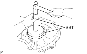
- SST
- 09550-60010
09950-60020 (09951-00680)
09950-70010 (09951-07100, 09951-00890)
- NOTICE:
- When replacing the bearing, be sure to replace it together with the outer race.
| 5. INSTALL FRONT DIFFERENTIAL CASE FRONT TAPERED ROLLER BEARING |
Using SST and a press, press in the front differential case front tapered roller bearing to the differential case.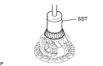
- SST
- 09550-60010
09950-60020 (09951-00680)
09950-70010 (09951-07100, 09951-00890)
- NOTICE:
- When replacing the bearing, be sure to replace it together with the outer race.
- When replacing a bearing of the differential case, replace both the front and rear bearings together.
- When replacing the bearing, be sure to replace it together with the outer race.
Using SST and a hammer, tap in the front differential case front tapered roller bearing outer race to the transaxle housing.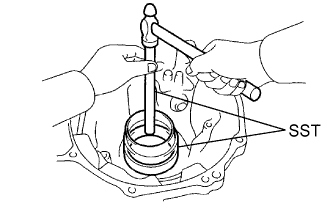
- SST
- 09550-60010
09950-60020 (09951-00680)
09950-70010 (09951-07100, 09951-00890)
- NOTICE:
- When replacing the bearing, be sure to replace it together with the outer race.
- Clearance is not allowed between the bearing and transaxle housing.
- When replacing the bearing, be sure to replace it together with the outer race.
| 6. ADJUST DIFFERENTIAL SIDE BEARING PRELOAD |
Install the differential assembly to the transaxle case.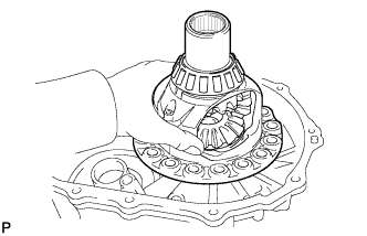
Clean the matching surfaces of the transaxle case and transaxle housing.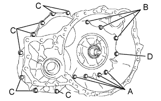
Install the transaxle housing to the transaxle case and tighten them with the 16 bolts.
- Torque:
- 22 N*m{ 224 kgf*cm , 16 ft.*lbf } for bolt A
- 29 N*m{ 295 kgf*cm , 21 ft.*lbf } for bolt B
- 29 N*m{ 295 kgf*cm , 21 ft.*lbf } for bolt C
- 22 N*m{ 224 kgf*cm , 16 ft.*lbf } for bolt D
- HINT:
- Each bolt length is indicated below.
- Bolt length:
- 50 mm (1.97 in.) for bolt A
50 mm (1.97 in.) for bolt B
42 mm (1.65 in.) for bolt C
72 mm (2.84 in.) for bolt D
- Usually, bolt A is a non-reusable bolt. In this case, however, it can be used after cleaning it.
- Each bolt length is indicated below.
Using SST, turn the differential assembly right and left 2 or 3 times to allow the bearing to settle.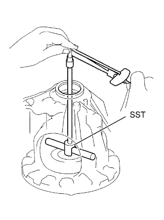
- SST
- 09564-32011
Using SST and a torque wrench, measure the turning torque of the differential.
- SST
- 09564-32011
- Torque:
- Standard turning torque at 60 rpm:
- 0.20 to 0.69 N*m{ 2.0 to 7.0 kgf*cm , 1.8 to 6.1 in.*lbf }
- HINT:
- If the turning torque is not within the specified value, refer to the table below and select a thrust washer so that the turning torque is within the specified value.
- Flange thickness:
Mark
Thickness
Mark
Thickness
0
2.00 mm (0.0787 in.)
J
2.025 mm (0.07972 in.)
1
2.05 mm (0.0807 in.)
K
2.075 mm (0.08169 in.)
2
2.10 mm (0.0827 in.)
L
2.125 mm (0.08366 in.)
3
2.15 mm (0.0846 in.)
M
2.175 mm (0.08563 in.)
4
2.20 mm (0.0866 in.)
N
2.225 mm (0.08760 in.)
5
2.25 mm (0.0886 in.)
P
2.275 mm (0.08957 in.)
6
2.30 mm (0.0906 in.)
Q
2.325 mm (0.09154 in.)
7
2.35 mm (0.0925 in.)
R
2.375 mm (0.09350 in.)
8
2.40 mm (0.0945 in.)
S
2.425 mm (0.09547 in.)
9
2.45 mm (0.0965 in.)
T
2.475 mm (0.09744 in.)
A
2.50 mm (0.0984 in.)
U
2.525 mm (0.09941 in.)
B
2.55 mm (0.1004 in.)
V
2.575 mm (0.10138 in.)
C
2.60 mm (0.1024 in.)
W
2.625 mm (0.10335 in.)
D
2.65 mm (1.1043 in.)
X
2.675 mm (0.10531 in.)
E
2.70 mm (0.1063 in.)
Y
2.725 mm (0.10728 in.)
F
2.75 mm (0.1083 in.)
AA
2.775 mm (0.10925 in.)
G
2.80 mm (0.1102 in.)
AB
2.825 mm (0.11122 in.)
H
2.85 mm (0.1122 in.)
-
-
Remove the 16 bolts and the transaxle housing.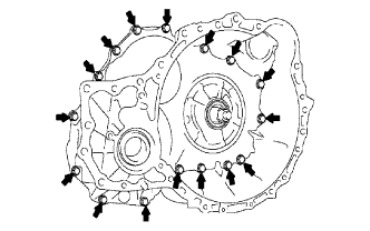
Remove the differential assembly.
| 7. INSTALL FRONT DIFFERENTIAL RING GEAR |
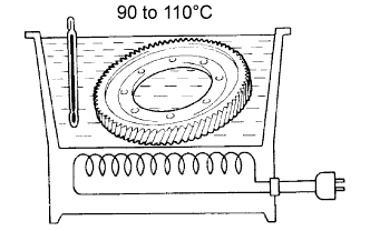 |
Using ATF and a heater, heat the front differential ring gear to 90 to 110°C (194.0 to 230.0°F).
- NOTICE:
- Do not overheat the ring gear to 110°C (230.0°F) or more.
Clean the contract surface of the front differential case.
Align the matchmarks, and install the front differential ring gear case quickly.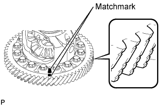
- NOTICE:
- Check the position and number of the grooves on each end face of the differential ring gear.
- Do not install the bolts while the ring gear is hot.
- Check the position and number of the grooves on each end face of the differential ring gear.
Tighten the 14 bolts.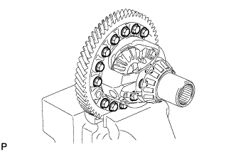
- Torque:
- 95 N*m{ 969 kgf*cm , 70 ft.*lbf }
- NOTICE:
- Tighten the bolts a little at a time in diagonal order.
| 8. INSTALL DIFFERENTIAL SIDE BEARING RETAINER OIL SEAL |
Coat the lip of a new oil seal with a small amount of MP grease.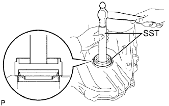
Using SST and a hammer, tap in the oil seal.
- SST
- 09223-15020
09950-70010 (09951-07100)
- Standard installation depth:
- -0.5 to 0.2 mm (-0.020 to 0.008 in.)
| 9. INSTALL TRANSAXLE HOUSING OIL SEAL |
Wrap vinyl tape around SST at the place 6.0 mm (0.236 in.) above the bottom end until the thickness of the wrapped tape is approximately 5.0 mm (0.197 in.).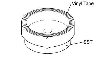
- SST
- 09950-60020
(09951-00730)
Coat the lip of a new oil seal with a small amount of MP grease.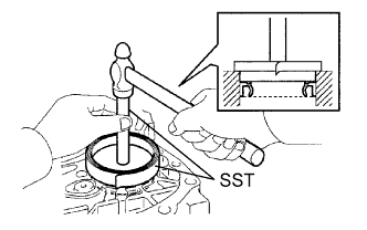
Using SST and a hammer, tap in the oil seal.
- SST
- 09950-60020
(09951-00730)
09950-70010 (09951-07150)
- Standard installation depth:
- 5.5 to 6.5 mm (0.217 to 0.256 in.)
- NOTICE:
- Stop pressing when the wrapped vinyl tape contacts the transaxle housing.