TERMINALS OF ECU
System information · Vehicles built from Nov 2005
| CHECK POWER STEERING ECU |
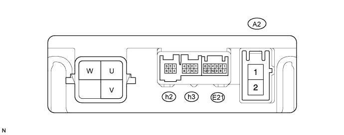

- HINT:
- Measurements cannot be performed on the h1 connector side of the power steering ECU.
| Symbols |
Wiring Color |
Terminal Description |
| U |
W |
U phase motor output |
| V |
B |
V phase motor output |
| W |
W-R |
W phase motor output |
Measure the voltage and resistance of the connectors.
Symbols (Terminal No.)
Wiring Color
Terminal Description
Condition
Specified Condition
PIG (A2-1) - PGND (A2-2)
W-B - W-B*1
L - W-B*2
Power source
Always
10 to 14 V
IG (E21-5) - PGND (A2-2)
L - W-B
IG power source
Ignition switch on (IG)
10 to 14 V
TRQ1 (h2-6) - TRQG (h2-1)
G - B
Torque sensor signal
Ignition switch on (IG)
Steering wheel not turned (without load)
2.3 to 2.7 V
Ignition switch on (IG)
Steering wheel turned to right with vehicle stopped
2.5 to 4.04 V
Ignition switch on (IG)
Steering wheel turned to left with vehicle stopped
0.95 to 2.5 V
TRQ2 (h2-2) - TRQG (h2-1)
Y - B
Torque sensor signal
Ignition switch on (IG)
Steering wheel not turned (without load)
2.3 to 2.7 V
Ignition switch on (IG)
Steering wheel turned to right with vehicle stopped
0.95 to 2.5 V
Ignition switch on (IG)
Steering wheel turned to left with vehicle stopped
2.5 to 4.04 V
TRQF (h2-4) - TRQG (h2-1)
W - B
Torque sensor reference voltage
Ignition switch on (IG)
3.35 to 3.37 V
TRQV (h2-3) - TRQG (h2-1)
R - B
Torque sensor voltage source
Ignition switch on (IG)
8.5 to 10.5 V
TRQG (h2-1) - Body ground
B - Body ground
Torque sensor ground
Always
Below 1 Ω
PGND (A2-2) - Body ground
W-B - Body ground
Power ground
Always
Below 1 Ω
C1 (h3-1) - PGND (A2-2)
R - W-B
Resolver output signal
Ignition switch on (IG)
Steering wheel is turned
0.68 to 4.42 V
C2 (h3-5) - PGND (A2-2)
L - W-B*1
Y - W-B*2
Resolver output signal
Ignition switch on (IG)
Steering wheel is turned
0.68 to 4.42 V
S1 (h3-2) - PGND (A2-2)
B - W-B
Resolver output signal
Ignition switch on (IG)
Steering wheel is turned
0.68 to 4.42 V
S2 (h3-6) - PGND (A2-2)
Y - W-B*1
L - W-B*2
Resolver output signal
Ignition switch on (IG)
Steering wheel is turned
0.68 to 4.42 V
R1 (h3-4) - PGND (A2-2)
W - W-B*1
G - W-B*1
Resolver excitation signal
Ignition switch on (IG)
Steering wheel is turned
2.9 to 5.1 V
R2 (h3-8) - PGND (A2-2)
G - W-B*1
W - W-B*2
Resolver excitation signal
Ignition switch on (IG)
Steering wheel is turned
2.9 to 5.1 V
CANH (E21-2) - CANL (E21-8)
Y - W
CAN communication line
Ignition switch off
54 to 69 Ω
- HINT:
- *1: for LHD
- *2: for RHD