Check CAN Bus Lines for Short Circuit (RHD Models)
Circuit diagnosis · Vehicles built Nov 2005 – Jul 2008
Versions by build date: Nov 2005 – Jul 2008 from Aug 2008
DESCRIPTION
There may be a short circuit between the CAN bus lines when the resistance between terminals 6 (CANH) and 14 (CANL) of the DLC3 is below 54 Ω.| Symptom |
Trouble Area |
| Resistance between terminals 6 (CANH) and 14 (CANL) of DLC3 is below 54 Ω. |
|
- HINT:
- *1: w/ ABS
- *2: w/ VSC
- *3: for 4WD
- *4: for 2WD with VSC and 4WD
WIRING DIAGRAM
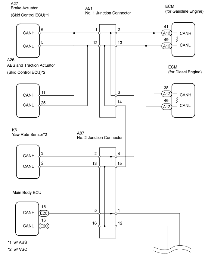

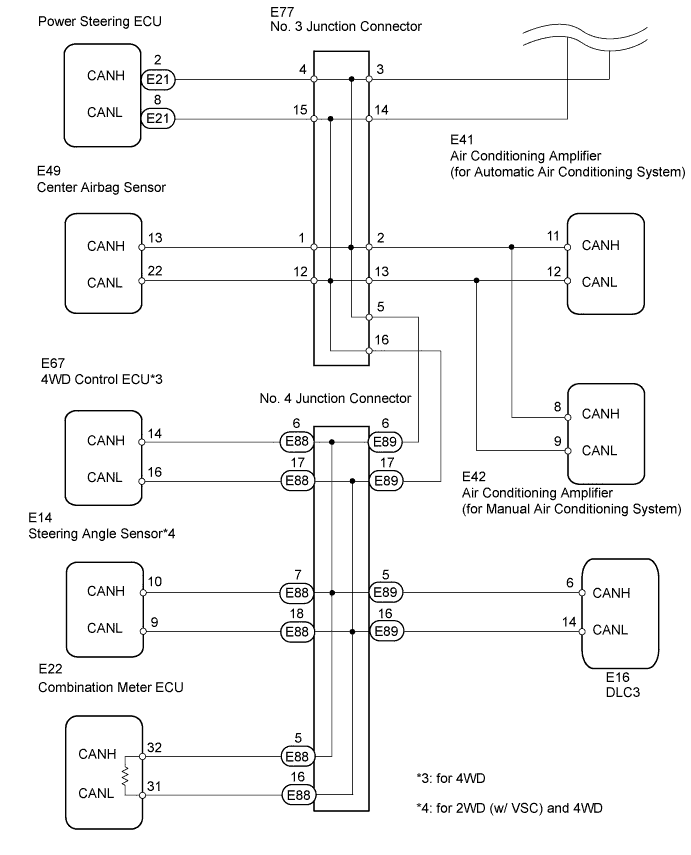
INSPECTION PROCEDURE
- NOTICE:
- Turn the ignition switch off before measuring the resistances of the main wire and the branch wire.
- For Auto:
After the ignition switch is turned off, check that the key reminder warning system is not in operation.
- For Reminder:
After the ignition switch is turned off, check that the key reminder warning system and light reminder buzzer are not in operation.
- Before measuring the resistance, leave the vehicle for at least 1 minute and do not operate the ignition switch, any switches or doors. If doors need to be opened in order to check connectors, open the doors and leave them open.
- Turn the ignition switch off before measuring the resistances of the main wire and the branch wire.
- HINT:
- Operating the ignition switch, any switches or any doors triggers related ECU and sensor communication with the CAN, which causes resistance variation.
| 1. CHECK CAN BUS LINES FOR SHORT CIRCUIT (DLC3 BRANCH WIRE) |

Disconnect the E89 No. 4 junction connector.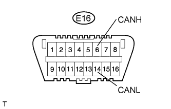
Measure the resistance of the DLC3.
- Standard resistance:
Tester Connection
Condition
Specified Condition
E16-6 (CANH) - E16-14 (CANL)
Ignition switch off
1 MΩ or more
|
|
||||

| OK | |
 |
| 2. CONNECT CONNECTOR |
Reconnect the E89 No. 4 junction connector.
| NEXT | |
|
| 3. CHECK CAN BUS LINES FOR SHORT CIRCUIT (NO. 1 JUNCTION CONNECTOR SIDE) |
Disconnect the A51 No. 1 junction connector.
Measure the resistance of the DLC3.
- Standard resistance:
Tester Connection
Condition
Specified Condition
E16-6 (CANH) - E16-14 (CANL)
Ignition switch off
108 to 132 Ω
|
|
||||

| NG | |
|
| 4. CHECK CAN BUS LINES FOR SHORT CIRCUIT (NO. 1 JUNCTION CONNECTOR - NO. 2 JUNCTION CONNECTOR) |
Disconnect the E87 No. 2 junction connector.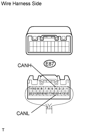
Measure the resistance of the wire harness side connector.
- Standard resistance:
Tester Connection
Condition
Specified Condition
E87-4 (CANH) - E87-15 (CANL)
Ignition switch off
1 MΩ or more
|
|
||||
| OK | |
|
| 5. CONNECT CONNECTOR |
Reconnect the A51 No. 1 junction connector.
Reconnect the E87 No. 2 junction connector.
| NEXT | |
|
| 6. CHECK CAN BUS LINES FOR SHORT CIRCUIT (NO. 1 JUNCTION CONNECTOR, NO. 2 JUNCTION CONNECTOR SIDE) |
Disconnect the E87 No. 2 junction connector.
Measure the resistance of the DLC3.
- Standard resistance:
Tester Connection
Condition
Specified Condition
E16-6 (CANH) - E16-14 (CANL)
Ignition switch off
108 to 132 Ω
|
|
||||
| NG | |
|
| 7. CHECK CAN BUS LINES FOR SHORT CIRCUIT (NO. 2 JUNCTION CONNECTOR - NO. 3 JUNCTION CONNECTOR) |
Disconnect the E77 No. 3 junction connector.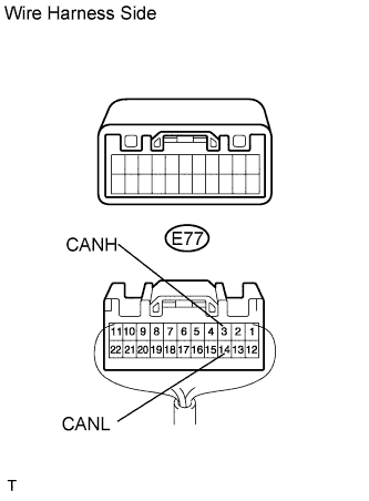
Measure the resistance of the wire harness side connector.
- Standard resistance:
Tester Connection
Condition
Specified Condition
E77-3 (CANH) - E77-14 (CANL)
Ignition switch off
1 MΩ or more
|
|
||||
| OK | |
|
| 8. CONNECT CONNECTOR |
Reconnect the E87 No. 2 junction connector.
Reconnect the E77 No. 3 junction connector.
| NEXT | |
|
| 9. CHECK CAN BUS LINES FOR SHORT CIRCUIT (NO. 1 JUNCTION CONNECTOR, NO. 2 JUNCTION CONNECTOR, NO. 3 JUNCTION CONNECTOR SIDE) |
Disconnect the E77 No. 3 junction connector.
Measure the resistance of the DLC3.
- Standard resistance:
Tester Connection
Condition
Specified Condition
E16-6 (CANH) - E16-14 (CANL)
Ignition switch off
108 to 132 Ω
|
|
||||
| NG | |
|
| 10. CHECK CAN BUS LINES FOR SHORT CIRCUIT (NO. 3 JUNCTION CONNECTOR - NO. 4 JUNCTION CONNECTOR) |
Disconnect the E89 No. 4 junction connector.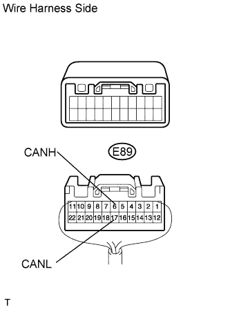
Measure the resistance of the wire harness side connector.
- Standard resistance:
Tester Connection
Condition
Specified Condition
E89-6 (CANH) - E89-17 (CANL)
Ignition switch off
1 MΩ or more
|
|
||||
| OK | |
|
| 11. CONNECT CONNECTOR |
Reconnect the E77 No. 3 junction connector.
Reconnect the E89 No. 4 junction connector.
| NEXT | |
|
| 12. CHECK CAN BUS LINES FOR SHORT CIRCUIT (NO. 4 JUNCTION CONNECTOR - 4WD CONTROL ECU) |
- NOTICE:
- For vehicles without 4WD, go to "CHECK CAN BUS LINES FOR SHORT CIRCUIT (NO. 4 JUNCTION CONNECTOR - STEERING ANGLE SENSOR)".
Disconnect the E88 No. 4 junction connector.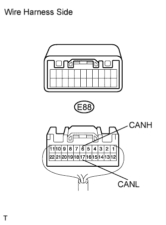
Measure the resistance of the wire harness side connector.
- Result:
Tester Connection
Condition
Specified Condition
Proceed to
E88-6 (CANH) - E88-17 (CANL)
Ignition switch off
Below 1 Ω
A
E88-6 (CANH) - E88-17 (CANL)
Ignition switch off
Other
B
|
|
||||
| B | |
|
| 13. CHECK CAN BUS LINES FOR SHORT CIRCUIT (NO. 4 JUNCTION CONNECTOR - STEERING ANGLE SENSOR) |
- NOTICE:
- For vehicles without 2WD with VSC and 4WD, go to "CHECK CAN BUS LINES FOR SHORT CIRCUIT (NO. 4 JUNCTION CONNECTOR - COMBINATION METER ECU)".
Measure the resistance of the wire harness side connector.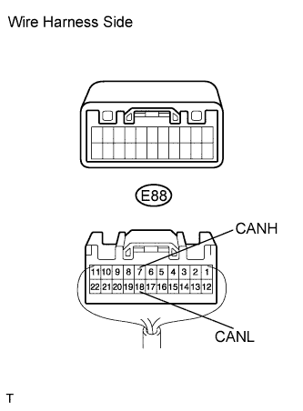
- Result:
Tester Connection
Condition
Specified Condition
Proceed to
E88-7 (CANH) - E88-18 (CANL)
Ignition switch off
Below 1 Ω
A
E88-7 (CANH) - E88-18 (CANL)
Ignition switch off
Other
B
|
|
||||
| B | |
|
| 14. CHECK CAN BUS LINES FOR SHORT CIRCUIT (NO. 4 JUNCTION CONNECTOR - COMBINATION METER ECU) |
Measure the resistance of the wire harness side connector.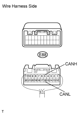
- Result:
Tester Connection
Condition
Specified Condition
Proceed to
E88-5 (CANH) - E88-16 (CANL)
Ignition switch off
Below 1 Ω
A
E88-5 (CANH) - E88-16 (CANL)
Ignition switch off
Other
B
|
|
||||
| B | ||
 |
||
| ||
| 15. CONNECT CONNECTOR |
Reconnect the E88 No. 4 junction connector.
| NEXT | |
|
| 16. CHECK CAN BUS LINES FOR SHORT CIRCUIT (4WD CONTROL ECU) |
Disconnect the E67 4WD control ECU connector.
Measure the resistance of the DLC3.
- Standard resistance:
Tester Connection
Condition
Specified Condition
E16-6 (CANH) - E16-14 (CANL)
Ignition switch off
54 to 69 Ω
|
|
||||
| OK | ||
|
||
| ||
| 17. CONNECT CONNECTOR |
Reconnect the E88 No. 4 junction connector.
| NEXT | |
|
| Go to step 15 |
| 18. CHECK CAN BUS LINES FOR SHORT CIRCUIT (STEERING ANGLE SENSOR) |
Disconnect the E14 steering angle sensor connector.
Measure the resistance of the DLC3.
- Standard resistance:
Tester Connection
Condition
Specified Condition
E16-6 (CANH) - E16-14 (CANL)
Ignition switch off
54 to 69 Ω
|
|
||||
| OK | ||
|
||
| ||
| 19. CONNECT CONNECTOR |
Reconnect the E88 No. 4 junction connector.
| NEXT | |
|
| Go to step 18 |
| 20. CHECK CAN BUS LINES FOR SHORT CIRCUIT (COMBINATION METER ECU) |
Disconnect the E22 combination meter ECU connector.
Measure the resistance of the DLC3.
- Standard resistance:
Tester Connection
Condition
Specified Condition
E16-6 (CANH) - E16-14 (CANL)
Ignition switch off
108 to 132 Ω
|
|
||||
| OK | ||
|
||
| ||
| 21. CHECK CAN BUS LINES FOR SHORT CIRCUIT (NO. 1 JUNCTION CONNECTOR - BRAKE ACTUATOR) |
- NOTICE:
- For vehicles without ABS, go to "CHECK CAN BUS LINES FOR SHORT CIRCUIT (NO. 1 JUNCTION CONNECTOR - ABS AND TRACTION ACTUATOR)".
Measure the resistance of the wire harness side connector.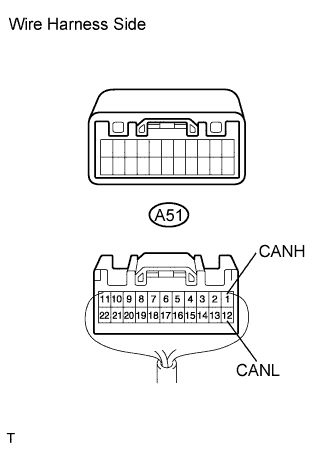
- Result:
Tester Connection
Condition
Specified Condition
Proceed to
A51-1 (CANH) - A51-12 (CANL)
Ignition switch off
Below 1 Ω
A
A51-1 (CANH) - A51-12 (CANL)
Ignition switch off
Other
B
|
|
||||
| B | |
|
| 22. CHECK CAN BUS LINES FOR SHORT CIRCUIT (NO. 1 JUNCTION CONNECTOR - ABS AND TRACTION ACTUATOR) |
- NOTICE:
- For vehicles without VSC, go to "CHECK CAN BUS LINES FOR SHORT CIRCUIT (NO. 1 JUNCTION CONNECTOR - ECM)".
Measure the resistance of the wire harness side connector.
- Result:
Tester Connection
Condition
Specified Condition
Proceed to
A51-1 (CANH) - A51-12 (CANL)
Ignition switch off
Below 1 Ω
A
A51-1 (CANH) - A51-12 (CANL)
Ignition switch off
Other
B
|
|
||||
| B | |
|
| 23. CHECK CAN BUS LINES FOR SHORT CIRCUIT (NO. 1 JUNCTION CONNECTOR - ECM) |
Measure the resistance of the wire harness side connector.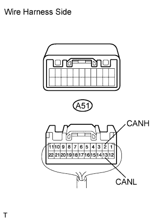
- Result:
Tester Connection
Condition
Specified Condition
Proceed to
A51-2 (CANH) - A51-13 (CANL)
Ignition switch off
Below 1 Ω
A
A51-2 (CANH) - A51-13 (CANL)
Ignition switch off
Other
B
|
|
||||
| B | ||
|
||
| ||
| 24. CONNECT CONNECTOR |
Reconnect the A51 No. 1 junction connector.
| NEXT | |
|
| 25. CHECK CAN BUS LINES FOR SHORT CIRCUIT (BRAKE ACTUATOR) |
Disconnect the A27 brake actuator (skid control ECU) connector.
Measure the resistance of the DLC3.
- Standard resistance:
Tester Connection
Condition
Specified Condition
E16-6 (CANH) - E16-14 (CANL)
Ignition switch off
54 to 69 Ω
|
|
||||
| OK | ||
|
||
| ||
| 26. CONNECT CONNECTOR |
Reconnect the A51 No. 1 junction connector.
| NEXT | |
|
| Go to step 24 |
| 27. CHECK CAN BUS LINES FOR SHORT CIRCUIT (ABS AND TRACTION ACTUATOR) |
Disconnect the A26 ABS and traction actuator (skid control ECU) connector.
Measure the resistance of the DLC3.
- Standard resistance:
Tester Connection
Condition
Specified Condition
E16-6 (CANH) - E16-14 (CANL)
Ignition switch off
54 to 69 Ω
|
|
||||
| OK | ||
|
||
| ||
| 28. CONNECT CONNECTOR |
Reconnect the A51 No. 1 junction connector.
| NEXT | |
|
| Go to step 27 |
| 29. CHECK CAN BUS LINES FOR SHORT CIRCUIT (ECM) |
Disconnect the A12 ECM connector.
Measure the resistance of the DLC3.
- Standard resistance:
Tester Connection
Condition
Specified Condition
E16-6 (CANH) - E16-14 (CANL)
Ignition switch off
108 to 132 Ω
|
|
||||
| OK | ||
|
||
| ||
| 30. CHECK CAN BUS LINES FOR SHORT CIRCUIT (NO. 2 JUNCTION CONNECTOR - YAW RATE SENSOR) |
- NOTICE:
- For vehicles without VSC, go to "CHECK CAN BUS LINES FOR SHORT CIRCUIT (NO. 2 JUNCTION CONNECTOR - MAIN BODY ECU)".
Measure the resistance of the wire harness side connector.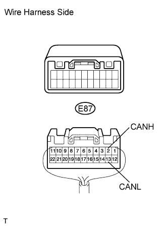
- Result:
Tester Connection
Condition
Specified Condition
Proceed to
E87-2 (CANH) - E87-13 (CANL)
Ignition switch off
Below 1 Ω
A
E87-2 (CANH) - E87-13 (CANL)
Ignition switch off
Other
B
|
|
||||
| B | |
|
| 31. CHECK CAN BUS LINES FOR SHORT CIRCUIT (NO. 2 JUNCTION CONNECTOR - MAIN BODY ECU) |
Measure the resistance of the wire harness side connector.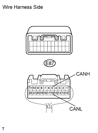
- Result:
Tester Connection
Condition
Specified Condition
Proceed to
E87-5 (CANH) - E87-16 (CANL)
Ignition switch off
Below 1 Ω
A
E87-5 (CANH) - E87-16 (CANL)
Ignition switch off
Other
B
|
|
||||
| B | ||
|
||
| ||
| 32. CONNECT CONNECTOR |
Reconnect the E87 No. 2 junction connector.
| NEXT | |
|
| 33. CHECK CAN BUS LINES FOR SHORT CIRCUIT (YAW RATE SENSOR) |
Disconnect the K6 yaw rate sensor connector.
Measure the resistance of the DLC3.
- Standard resistance:
Tester Connection
Condition
Specified Condition
E16-6 (CANH) - E16-14 (CANL)
Ignition switch off
54 to 69 Ω
|
|
||||
| OK | ||
|
||
| ||
| 34. CONNECT CONNECTOR |
Reconnect the E87 No. 2 junction connector.
| NEXT | |
|
| 35. CHECK CAN BUS LINES FOR SHORT CIRCUIT (MAIN BODY ECU) |
Disconnect the E20 main body ECU connector.
Measure the resistance of the DLC3.
- Standard resistance:
Tester Connection
Condition
Specified Condition
E16-6 (CANH) - E16-14 (CANL)
Ignition switch off
54 to 69 Ω
|
|
||||
| OK | ||
|
||
| ||
| 36. CHECK CAN BUS LINES FOR SHORT CIRCUIT (NO. 3 JUNCTION CONNECTOR - AIR CONDITIONING AMPLIFIER) |
Measure the resistance of the wire harness side connector.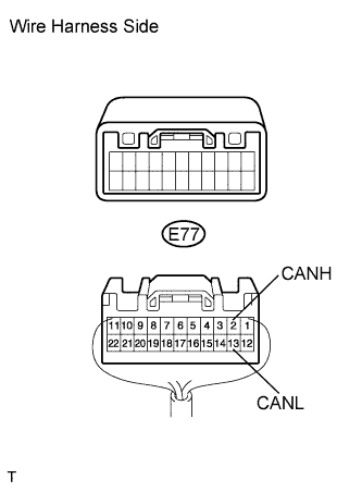
- Result:
Tester Connection
Condition
Specified Condition
Proceed to
E77-2 (CANH) - E77-13 (CANL)
Ignition switch off
Below 1 Ω
A
E77-2 (CANH) - E77-13 (CANL)
Ignition switch off
Other
B
|
|
||||
| B | |
|
| 37. CHECK CAN BUS LINES FOR SHORT CIRCUIT (NO. 3 JUNCTION CONNECTOR - POWER STEERING ECU) |
Measure the resistance of the wire harness side connector.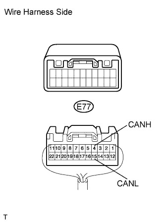
- Result:
Tester Connection
Condition
Specified Condition
Proceed to
E77-4 (CANH) - E77-15 (CANL)
Ignition switch off
Below 1 Ω
A
E77-4 (CANH) - E77-15 (CANL)
Ignition switch off
Other
B
|
|
||||
| B | |
|
| 38. CHECK CAN BUS LINES FOR SHORT CIRCUIT (NO. 3 JUNCTION CONNECTOR - CENTER AIRBAG SENSOR ASSEMBLY) |
Measure the resistance of the wire harness side connector.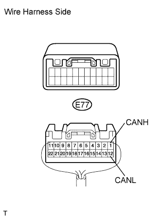
- Result:
Tester Connection
Condition
Specified Condition
Proceed to
E77-1 (CANH) - E77-12 (CANL)
Ignition switch off
Below 1 Ω
A
E77-1 (CANH) - E77-12 (CANL)
Ignition switch off
Other
B
|
|
||||
| B | ||
|
||
| ||
| 39. CONNECT CONNECTOR |
Reconnect the E77 No. 3 junction connector.
| NEXT | |
|
| 40. CHECK CAN BUS LINES FOR SHORT CIRCUIT (AIR CONDITIONING AMPLIFIER) |
Disconnect the E41*1 or E42*2 air conditioning amplifier connector.
- HINT:
- *1: for Automatic air conditioning system.
- *2: for Manual air conditioning system.
- *1: for Automatic air conditioning system.
Measure the resistance of the DLC3.
- Standard resistance:
Tester Connection
Condition
Specified Condition
E16-6 (CANH) - E16-14 (CANL)
Ignition switch off
54 to 69 Ω
|
|
||||
| OK | ||
|
||
| ||
| 41. CONNECT CONNECTOR |
Reconnect the E77 No. 3 junction connector.
| NEXT | |
|
| 42. CHECK CAN BUS LINES FOR SHORT CIRCUIT (POWER STEERING ECU) |
Disconnect the E21 power steering ECU connector.
Measure the resistance of the DLC3.
- Standard resistance:
Tester Connection
Condition
Specified Condition
E16-6 (CANH) - E16-14 (CANL)
Ignition switch off
54 to 69 Ω
|
|
||||
| OK | ||
|
||
| ||
| 43. CONNECT CONNECTOR |
Reconnect the E77 No. 3 junction connector.
| NEXT | |
|
| 44. CHECK CAN BUS LINES FOR SHORT CIRCUIT (CENTER AIRBAG SENSOR ASSEMBLY) |
Disconnect the E49 center airbag sensor connector.
Measure the resistance of the DLC3.
- Standard resistance:
Tester Connection
Condition
Specified Condition
E16-6 (CANH) - E16-14 (CANL)
Ignition switch off
54 to 69 Ω
|
|
||||
| OK | ||
|
||
| ||