2005-2008 RAV4 · Service Manual BODY

INSTALLATION

Removal / installation · Vehicles built Jan 2007 – Jul 2007

Versions by build date: Nov 2005 – Dec 2006 Jan 2007 – Jul 2007 from Aug 2007


1. INSTALL NO. 1 ROOF SILENCER PAD
  1. w/o Sliding Roof:

    1. Install the 5 silencer pads.

  1. w/ Sliding Roof:

    1. Install the 2 silencer pads.


2. INSTALL NO. 3 ROOF SILENCER PAD

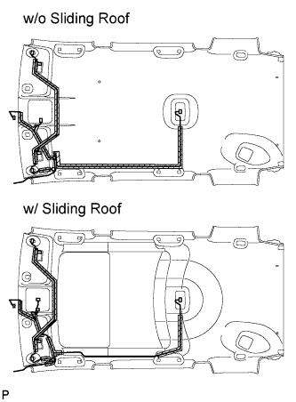
3. INSTALL ANTENNA CORD SUB-ASSEMBLY

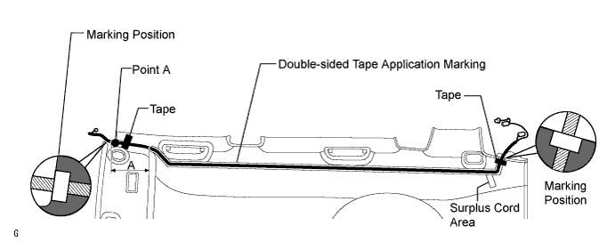
  1. for Short Body (w/o Sliding Roof):

    1. Apply new double-sided tape as shown in the illustration.

      HINT:
      There are no installation markings in area A in the illustration. Therefore, apply the double-sided tape toward point A.

    2. Align the antenna cord masking tape and the edge of the roof headlining. Attach the antenna cord along the double-sided tape.

      HINT:
      Place any extra antenna cord length in the surplus cord area shown in the illustration.

    3. Apply tape to both ends of the antenna cord to fix the cord in place.

      B135634E01

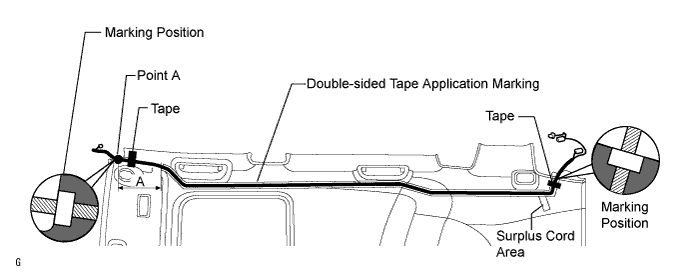
  1. for Short Body (w/ Sliding Roof):

    1. Apply new double-sided tape as shown in the illustration.

      HINT:
      There are no installation markings in area A in the illustration. Therefore, apply the double-sided tape toward point A.

    2. Align the antenna cord masking tape and the edge of the roof headlining. Attach the antenna cord along the double-sided tape.

      HINT:
      Place any extra antenna cord length in the surplus cord area shown in the illustration.

    3. Apply tape to both ends of the antenna cord to fix the cord in place.

      B135636E01

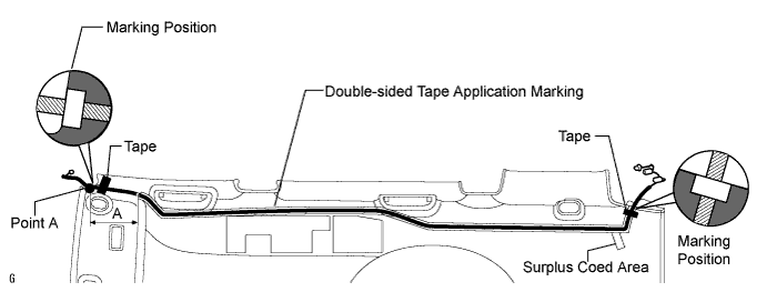
  1. for Long Body (w/o Sliding Roof):

    1. Apply new double-sided tape as shown in the illustration.

      HINT:
      There are no installation markings in area A in the illustration. Therefore, apply the double-sided tape toward point A.

    2. Align the antenna cord masking tape and the edge of the roof headlining. Attach the antenna cord along the double-sided tape.

      HINT:
      Place any extra antenna cord length in the surplus cord area shown in the illustration.

    3. Apply tape to both ends of the antenna cord to fix the cord in place.

      B135635E01

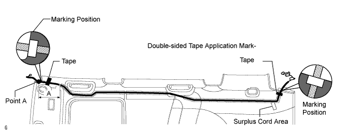
  1. for Long Body (w/ Sliding Roof):

    1. Apply new double-sided tape as shown in the illustration.

      HINT:
      There are no installation markings in area A in the illustration. Therefore, apply the double-sided tape toward point A.

    2. Align the antenna cord masking tape and the edge of the roof headlining. Attach the antenna cord along the double-sided tape.

      HINT:
      Place any extra antenna cord length in the surplus cord area shown in the illustration.

    3. Apply tape to both ends of the antenna cord to fix the cord in place.

      B135637E01


4. INSTALL NO. 1 ROOF WIRE

  1. B130238E01
    Only when replacing the roof headlining:

    1. Align the marking, and then install the wire harness with tape.

      HINT:
      Be careful that dirt or foreign objects do not stick to the adhesive part when peeling off the double-sided tape.

    2. Attach the roof wire harness along the adhesive part.

      NOTICE:
      The roof wire harness should be attached securely.


5. INSTALL NO. 1 ROOF HEADLINING SUPPORT

6. INSTALL NO. 2 ROOF HEADLINING SUPPORT

7. INSTALL NO. 3 ROOF HEADLINING SUPPORT

8. INSTALL NO. 4 ROOF HEADLINING SUPPORT

9. INSTALL ROOF HEADLINING ASSEMBLY
  1. w/o Sliding Roof:

    1. Install the headlining with the 4 clips.

  1. w/ Sliding Roof:

    1. Install the headlining with the 2 clips.

    2. Connect the connector to the sliding roof drive gear.

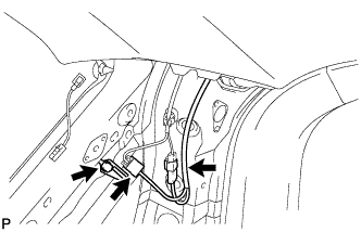
  1. Connect the antenna cord sub-assembly.

    1. B135485
      Install the bracket's bolt.

    2. Attach the clamp of the antenna cord.

    3. Connect the 2 antenna cord connectors to the rear pillar RH.

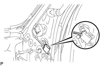
    4. B135492
      Connect the antenna cord connector to the front pillar RH.

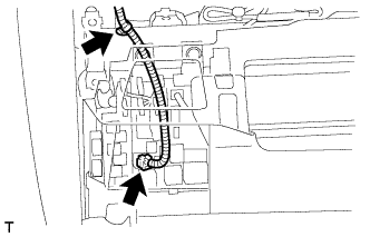
  1. B131381
    Connect the No. 1 roof wire.

    1. Connect the connector to the roof wire.

    2. Attach the clamp of the roof wire.


10. INSTALL SUN ROOF OPENING TRIM MOULDING

11. INSTALL SHOULDER BELT ANCHOR COVER RH

B133646E01
  1. Install the cover with the 4 claws.


12. INSTALL CHILD RESTRAINT SEAT TETHER ANCHOR COVER

B131611
  1. Install the cover with the 4 claws.


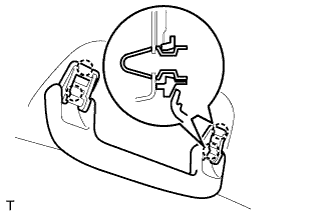
13. INSTALL REAR ASSIST GRIP ASSEMBLY

  1. B131004
    Attach the 4 claws to install the assist grip.


14. INSTALL ASSIST GRIP COVER (for Rear Grip)
  1. Attach the 4 claws to install the 2 assist grip covers.


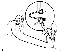
15. INSTALL ASSIST GRIP SUB-ASSEMBLY

  1. B131003
    Attach the 4 claws to install the assist grip.


16. INSTALL ASSIST GRIP COVER (for Front Grip)
  1. Attach the 4 claws to install the 2 assist grip covers.


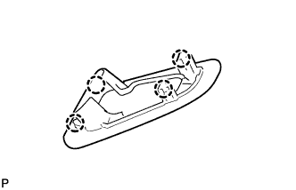
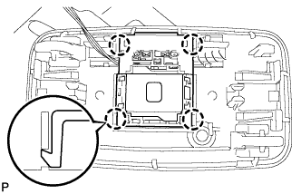
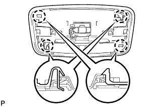
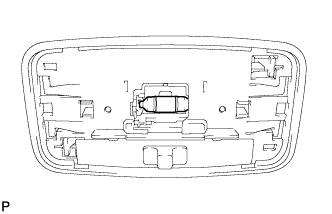
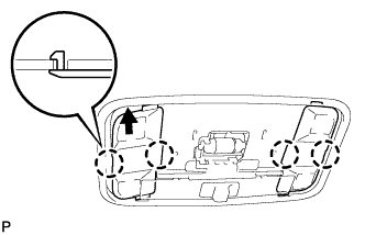
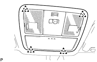
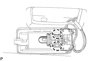
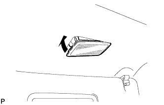
17. INSTALL ROOM LIGHT ASSEMBLY

B132731
  1. Attach the 4 claws to install the room light switch base.

  1. B131450
    Attach the 4 claws to install the room light.

  1. B131449
    Install the bulb to the room light switch base.

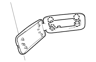
  1. B132732
    Attach the 4 claws and install the 2 covers.


18. INSTALL MAP LIGHT ASSEMBLY

B131951
  1. Connect the light connector.

  1. Attach the 4 clips to install the map light.


19. INSTALL VANITY LIGHT ASSEMBLY

  1. B131425
    Attach the 2 claws and install the vanity light lens to the vanity light.

  1. B131424
    Install the vanity light.


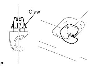
20. INSTALL VISOR HOLDER

  1. B122230E02
    Set the claws of the visor holder as shown in the illustration.

  1. Insert the visor holder to install it.


21. INSTALL VISOR ASSEMBLY LH

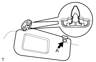
B131006E01
  1. Attach the 2 claws to install the visor.

  1. Install portion A of the visor to the visor holder.

  1. Attach the 4 claws to install the visor bracket cover.


22. INSTALL VISOR ASSEMBLY RH

HINT:
Use the same procedures described for the LH side.


23. INSTALL REAR ROOM PARTITION NET HOOK LH

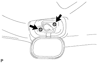
  1. B129710
    Install the net hook with the 2 screws.


24. INSTALL REAR ROOM PARTITION NET HOOK RH

HINT:
Use the same procedures described for the LH side.


25. INSTALL INNER ROOF SIDE GARNISH ASSEMBLY LH

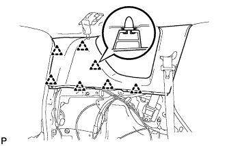
  1. B129708
    Attach the 7 clips to install the garnish.


26. INSTALL INNER ROOF SIDE GARNISH ASSEMBLY RH

HINT:
Use the same procedures described for the LH side.


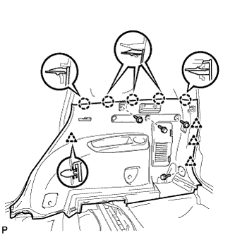
27. INSTALL DECK TRIM SIDE PANEL ASSEMBLY LH

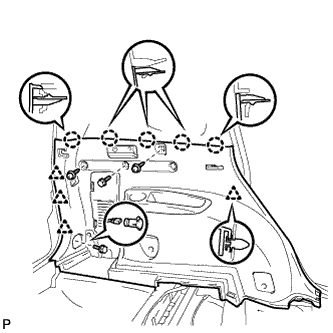
  1. B129706
    Install the belt hanger to the trim board.

  1. Connect the power outlet socket connector.

  1. Attach the 4 clips and 5 claws to install the trim board.

  1. Install the 2 screws and 2 bolts.

  1. B137546
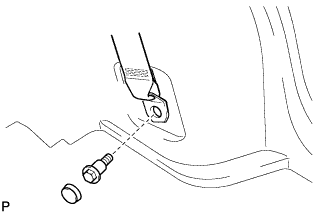
    Connect the rear No.1 seat belt's floor anchor.

    1. Connect the floor anchor with the bolt.

      Torque:
      42 N*m{ 428 kgf*cm , 31 ft.*lbf }

    2. Install the anchor cover.


28. INSTALL DECK TRIM SIDE PANEL ASSEMBLY RH

  1. B129707
    Install the belt hanger to the trim board.

  1. Attach the 4 clips and 5 claws to install the trim board.

  1. Install the 2 screws and 2 bolts.

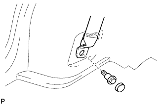
  1. B137547
    Connect the rear No.1 seat belt's floor anchor.

    1. Connect the floor anchor with the bolt.

      Torque:
      42 N*m{ 428 kgf*cm , 31 ft.*lbf }

    2. Install the anchor cover.


29. INSTALL TETHER ANCHOR BRACKET SUB-ASSEMBLY

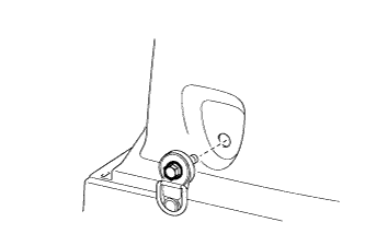
  1. B135674
    Install the tether anchor bracket with the bolt.

    Torque:
    42 N*m{ 428 kgf*cm , 31 ft.*lbf }


30. INSTALL RECLINING REMOTE CONTROL LEVER BEZEL LH

  1. B132537
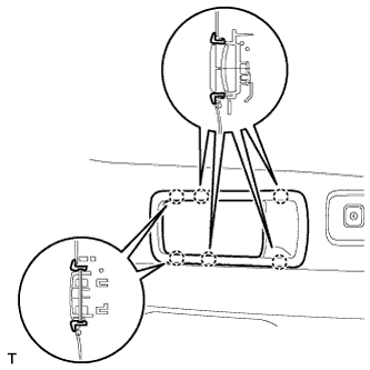
    Attach the 6 claws to install the bezel.


31. INSTALL RECLINING REMOTE CONTROL LEVER BEZEL RH

  1. B135482
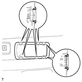
    Attach the 6 claws to install the bezel.


32. INSTALL REAR FLOOR FINISH PLATE

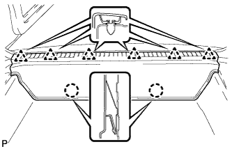
  1. B129704
    Attach the 2 claws and 6 clips to install the finish plate.


33. INSTALL BACK DOOR WEATHERSTRIP

34. INSTALL REAR FLOOR NO. 1 MAT SUPPORT SIDE PLATE

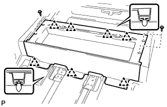
B129705
  1. Attach the 7 clips to install the side plate.

  1. Install the 4 screws.


35. INSTALL REAR FLOOR NO. 3 BOARD

36. INSTALL REAR FLOOR NO. 2 BOARD

37. INSTALL DECK BOARD ASSEMBLY

38. INSTALL REAR FLOOR NO. 1 BOARD

39. INSTALL TONNEAU COVER ASSEMBLY

40. INSTALL PACKAGE TRAY TRIM POCKET SUB-ASSEMBLY

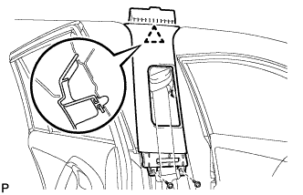
41. INSTALL CENTER PILLAR GARNISH LH

B129701
  1. Attach the clip to install the garnish.

  1. Install the 2 screws.


42. INSTALL CENTER PILLAR GARNISH RH

HINT:
Use the same procedures described for the LH side.


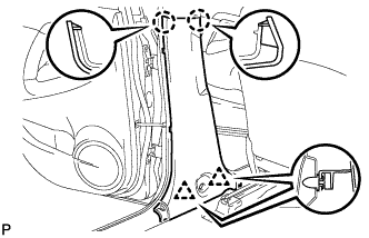
43. INSTALL LOWER CENTER PILLAR GARNISH LH

  1. B129700
    Attach the 2 claws and 2 clips to install the garnish.

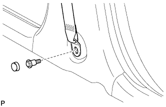
  1. B137545
    Connect the front seat outer belt's floor anchor.

    1. Connect the floor anchor with the bolt.

      Torque:
      42 N*m{ 428 kgf*cm , 31 ft.*lbf }

    2. Install the anchor cover.


44. INSTALL LOWER CENTER PILLAR GARNISH RH

HINT:
Use the same procedures described for the LH side.


45. INSTALL REAR DOOR OPENING TRIM WEATHERSTRIP LH

46. INSTALL REAR DOOR OPENING TRIM WEATHERSTRIP RH

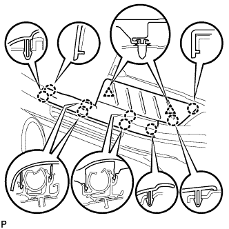
47. INSTALL REAR DOOR SCUFF PLATE LH

  1. B129703
    Attach the 9 claws and 2 clips to install the scuff plate.


48. INSTALL REAR DOOR SCUFF PLATE RH

HINT:
Use the same procedures described for the LH side.


49. INSTALL INSTRUMENT PANEL SUB-ASSEMBLY
  1. Attach the 6 clips and 5 claws to install the instrument panel.

  1. Connect the connectors and clamps.

  1. Install the 2 bolts and 2 screws.

    B129870

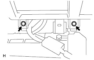
  1. Connect the passenger airbag connector.

  1. B129886
    Install the 2 bolts to the passenger airbag.

    Torque:
    20 N*m{ 204 kgf*cm , 15 ft.*lbf }


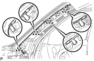
50. INSTALL FRONT PILLAR GARNISH LH
  1. w/ Curtain Shield Airbag:

    1. Remove the piece of cloth or nylon.

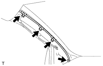
  1. B114316
    Install the 4 wire harness clamps.

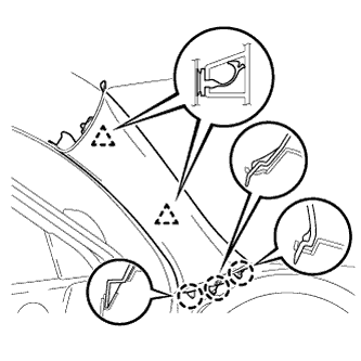
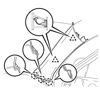
  1. B146179
    w/ Curtain Shield Airbag:

    1. Install 2 new clips to the front pillar garnish.

    2. Attach the 3 claws and 2 clips to install the garnish.

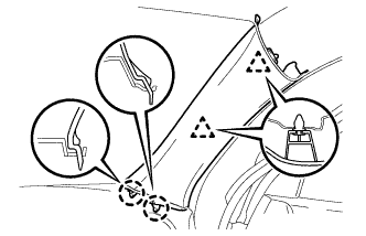
  1. w/o Curtain Shield Airbag:

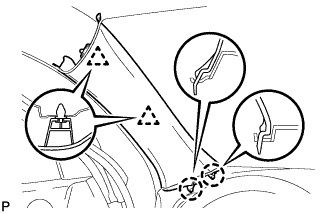
    1. B131215
      Attach the 2 clips and 2 claws to install the garnish.


51. INSTALL FRONT PILLAR GARNISH RH
  1. w/ Curtain Shield Airbag:

    1. Remove the piece of cloth or nylon.

  1. B135443
    Install the 4 antenna cord clamps.

  1. B146181
    w/ Curtain Shield Airbag:

    1. Install 2 new clips to the front pillar garnish.

    2. Attach the 3 claws and 2 clips to install the garnish.

  1. w/o Curtain Shield Airbag:

    1. B131379
      Attach the 2 clips and 2 claws to install the garnish.


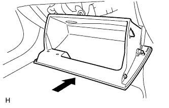
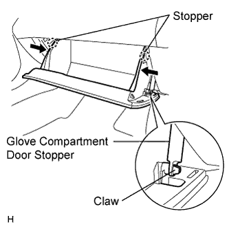
52. INSTALL GLOVE COMPARTMENT DOOR ASSEMBLY

B129887
  1. Attach the 2 hinges to install the door.

  1. B129889E03
    Attach the claw to the glove compartment door stopper.

  1. While pushing in the sides of the glove compartment door as indicated by the arrows in the illustration, close the door to engage it to the 2 stoppers.


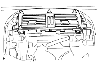
53. INSTALL INSTRUMENT PANEL REGISTER ASSEMBLY CENTER

B129890
  1. Attach the 5 clips to install the instrument panel register.


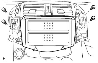
54. INSTALL STEREO OPENING COVER (w/o Radio Receiver)

B133002
  1. Attach the 4 clips to install the stereo opening cover.

  1. Install the 4 bolts.


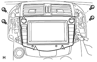
55. INSTALL RADIO RECEIVER (w/ Radio Receiver)

B129891
  1. Connect the connectors.

  1. Attach the 4 clips to install the radio receiver.

  1. Install the 4 bolts.


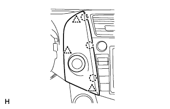
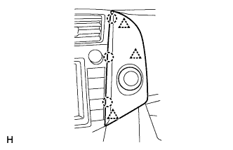
56. INSTALL NO. 2 INSTRUMENT CLUSTER FINISH PANEL CENTER

B140788
  1. Connect the connector.

  1. Attach the 3 clips and 3 claws to install the cluster finish panel.


57. INSTALL NO. 1 INSTRUMENT CLUSTER FINISH PANEL CENTER

B140787
  1. Connect the connector.

  1. Attach the 3 clips and 3 claws to install the cluster finish panel.


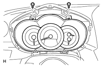
58. INSTALL COMBINATION METER ASSEMBLY

B129873
  1. Connect the connector.

  1. Attach the 2 clips to install the combination meter.

  1. Install the 2 screws.
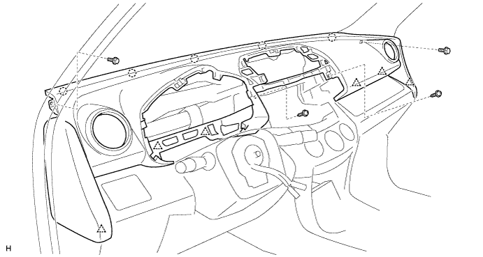

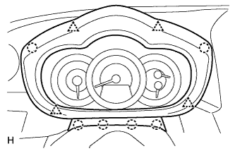
59. INSTALL INSTRUMENT CLUSTER FINISH PANEL ASSEMBLY

B129872
  1. Attach the 4 clips and 6 claws to install the instrument cluster finish panel.


60. INSTALL FRONT DOOR OPENING TRIM WEATHERSTRIP LH

61. INSTALL FRONT DOOR OPENING TRIM WEATHERSTRIP RH

62. INSTALL COWL SIDE TRIM BOARD LH

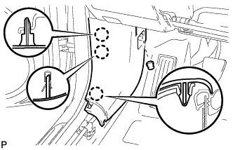
B129697
  1. Attach the 3 claws to install the trim board.

  1. Install the cap nut.


63. INSTALL COWL SIDE TRIM BOARD RH

HINT:
Use the same procedures described for the LH side.


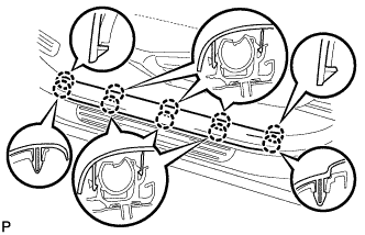
64. INSTALL FRONT DOOR SCUFF PLATE LH

  1. B129699
    Attach the 10 claws to install the scuff plate.


65. INSTALL FRONT DOOR SCUFF PLATE RH

HINT:
Use the same procedures described for the LH side.


66. CONNECT CABLE TO NEGATIVE BATTERY TERMINAL
← INSTALLATION (Nov 2005 – Dec 2006)INSTALLATION (from Aug 2007) →