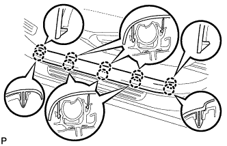
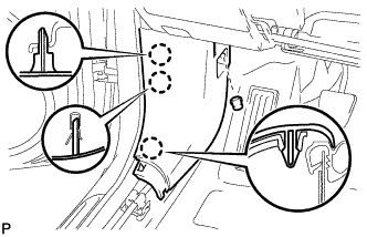
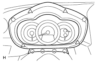
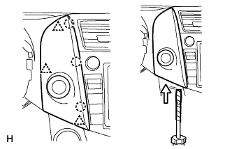
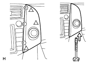
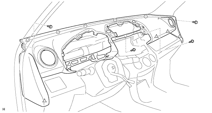
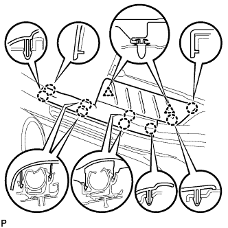
Using a screwdriver, detach the 4 clips, 6 claws and remove the instrument cluster finish panel.
HINT:
Tape the screwdriver tip before use.
9.
REMOVE COMBINATION METER ASSEMBLY
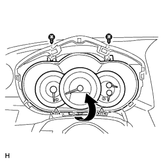
Remove the 2 screws.
Pull the combination meter as indicated by the arrow in the illustration to detach the 2 clips.
Disconnect the connector and remove the combination meter.
10.
REMOVE NO. 2 INSTRUMENT CLUSTER FINISH PANEL CENTER
Using a screwdriver, detach the 3 clips, 3 claws and remove the cluster finish panel, then disconnect the connector.
HINT:
Tape the screwdriver tip before use.
11.
REMOVE NO. 1 INSTRUMENT CLUSTER FINISH PANEL CENTER
Using a screwdriver, detach the 3 clips, 3 claws and remove the cluster finish panel, then disconnect the connector.
HINT:
Tape the screwdriver tip before use.
12.
REMOVE RADIO RECEIVER (w/ Radio Receiver)
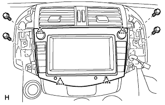
Remove the 4 bolts.
Detach the 4 clips, remove the radio receiver and then disconnect the connectors.
13.
REMOVE STEREO OPENING COVER (w/o Radio Receiver)
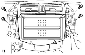
Remove the 4 bolts.
Detach the 4 clips and remove the stereo opening cover.
14.
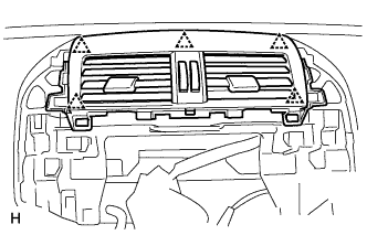
REMOVE INSTRUMENT PANEL REGISTER ASSEMBLY CENTER
Using a screwdriver, detach the 5 clips and remove the instrument panel register.
HINT:
Tape the screwdriver tip before use.
15.
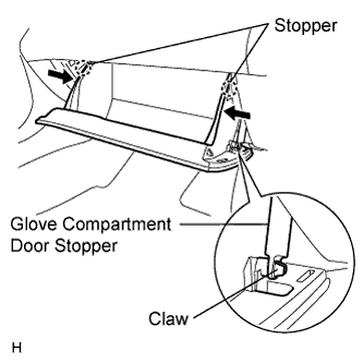
REMOVE GLOVE COMPARTMENT DOOR ASSEMBLY
Open the glove compartment door.
Detach the claw from the glove compartment door stopper.
While pushing in the sides of the glove compartment door as indicated by the arrows in the illustration, open the door to release it from the 2 stoppers.
Open the door until it is horizontal.
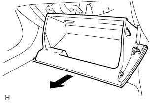
Pull the glove compartment door toward the rear of the vehicle to detach the 2 hinges and remove the glove compartment door.
16.
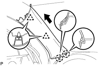
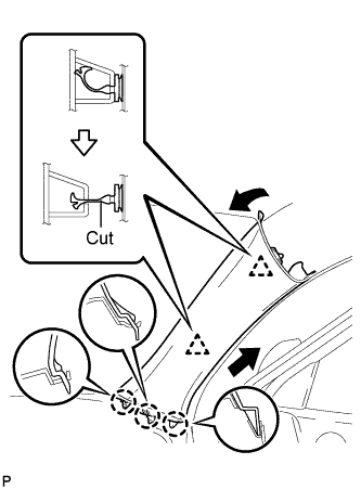
REMOVE FRONT PILLAR GARNISH LH
w/o Curtain Shield Airbag:
Using a clip remover, detach the 2 clips.
Pull the garnish in the direction indicated by the arrow in the illustration to detach the 2 claws. Then remove the garnish.
w/ Curtain Shield Airbag:
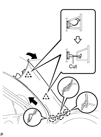
Detach the 2 clips.
Cut off the 2 clips.
Detach the 3 claws and remove the garnish.
Remove the 2 clips from the vehicle body.
NOTICE:
As the clips are cut, be sure to install new clips when installing the garnish.
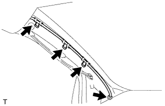
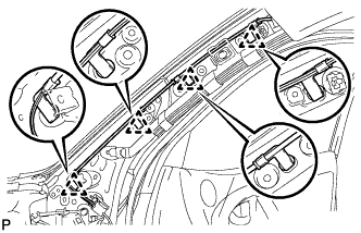
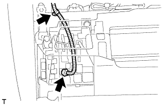
Using a clip remover, remove the 4 wiring harness clamps.
w/ Curtain Shield Airbag:
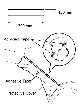
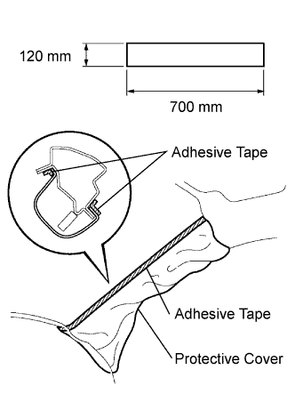
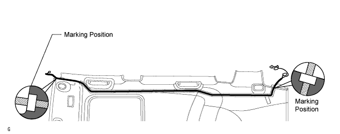
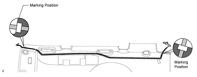
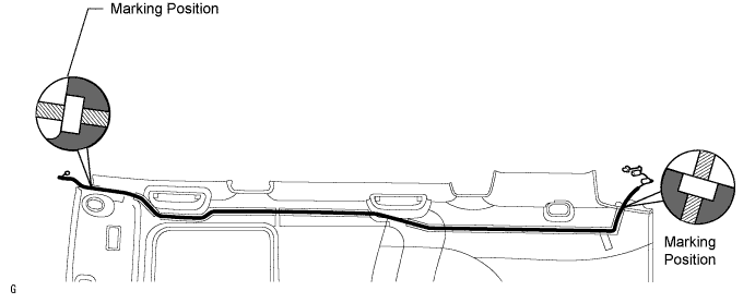
Thoroughly cover the airbag with cloth or nylon of 700 mm (27.56 in.) x 120 mm (4.72 in.) and fix the ends of the cover with adhesive tape, as shown in the illustration.
NOTICE:
Cover the curtain shield airbag with a protective cover as soon as the front pillar garnish is removed.
17.
REMOVE FRONT PILLAR GARNISH RH
w/o Curtain Shield Airbag:
Using a clip remover, detach the 2 clips.
Pull the garnish in the direction indicated by the arrow in the illustration to detach the 2 claws. Then remove the garnish.
w/ Curtain Shield Airbag:
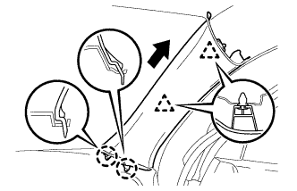
Detach the 2 clips.
Cut off the 2 clips.
Detach the 3 claws and remove the garnish.
Remove the 2 clips from the vehicle body.
NOTICE:
As the clips are cut, be sure to install new clips when installing the garnish.
Using a clip remover, remove the 4 antenna cord clamps.
w/ Curtain Shield Airbag:
Thoroughly cover the airbag with cloth or nylon of 700 mm (27.56 in.) x 120 mm (4.72 in.) and fix the ends of the cover with adhesive tape, as shown in the illustration.
NOTICE:
Cover the curtain shield airbag with a protective cover as soon as the front pillar garnish is removed.
18.
REMOVE INSTRUMENT PANEL SUB-ASSEMBLY
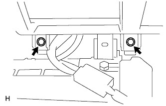
Remove the 2 bolts from the passenger airbag.
Disconnect the passenger airbag connector.
Remove the 2 bolts and 2 screws.
Disconnect the connectors and clamps.
Detach the 6 clips and 5 claws and remove the instrument panel.
19.
REMOVE REAR DOOR SCUFF PLATE LH
Using a screwdriver, detach the 9 claws.
HINT:
Tape the screwdriver tip before use.
Using a clip remover, detach the 2 clips and remove the garnish.
20.
REMOVE REAR DOOR SCUFF PLATE RH
HINT:
Use the same procedures described for the LH side.
21.
REMOVE REAR DOOR OPENING TRIM WEATHERSTRIP LH
22.
REMOVE REAR DOOR OPENING TRIM WEATHERSTRIP RH
23.
REMOVE LOWER CENTER PILLAR GARNISH LH
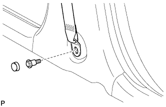
Disconnect the front seat outer belt's floor anchor.
Remove the anchor cover.
Remove the bolt and disconnect the floor anchor.
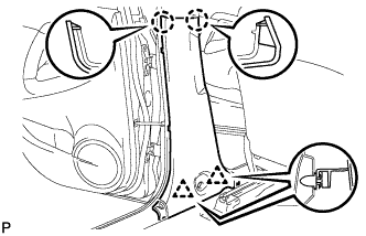
Using a screwdriver, detach the 2 claws.
HINT:
Tape the screwdriver tip before use.
Using a clip remover, detach the 2 clips and remove the garnish.
24.
REMOVE LOWER CENTER PILLAR GARNISH RH
HINT:
Use the same procedures described for the LH side.
25.
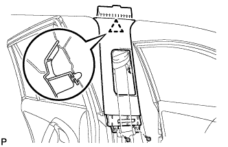
REMOVE CENTER PILLAR GARNISH LH
Remove the 2 screws.
Using a clip remover, detach the clip and remove the garnish.
26.
REMOVE CENTER PILLAR GARNISH RH
HINT:
Use the same procedures described for the LH side.
27.
REMOVE PACKAGE TRAY TRIM POCKET SUB-ASSEMBLY
28.
REMOVE TONNEAU COVER ASSEMBLY
29.
REMOVE REAR FLOOR NO. 1 BOARD
30.
REMOVE DECK BOARD ASSEMBLY
31.
REMOVE REAR FLOOR NO. 3 BOARD
32.
REMOVE REAR FLOOR NO. 2 BOARD
33.
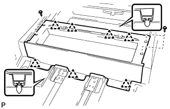
REMOVE REAR FLOOR NO. 1 MAT SUPPORT SIDE PLATE
Remove the 4 screws.
Using a clip remover, detach the 7 clips and remove the plate.
34.
REMOVE BACK DOOR WEATHERSTRIP
35.
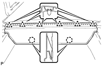
REMOVE REAR FLOOR FINISH PLATE
Using a clip remover, detach the 6 clips.
Detach the 2 claws and remove the finish plate.
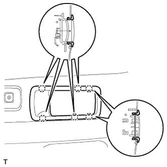
36.
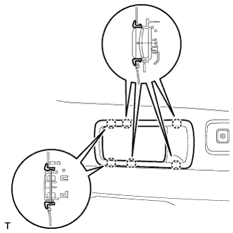
REMOVE RECLINING REMOTE CONTROL LEVER BEZEL LH
Using a screwdriver, detach the 6 claws and remove the bezel.
HINT:
Tape the screwdriver tip before use.
37.
REMOVE RECLINING REMOTE CONTROL LEVER BEZEL RH
Using a screwdriver, detach the 6 claws and remove the bezel.
HINT:
Tape the screwdriver tip before use.
38.
REMOVE TETHER ANCHOR BRACKET SUB-ASSEMBLY
Remove the bolt and tether anchor bracket.
39.
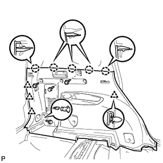
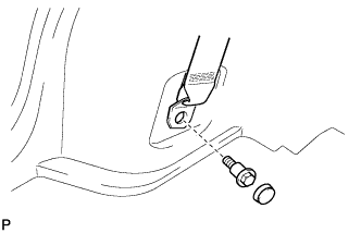
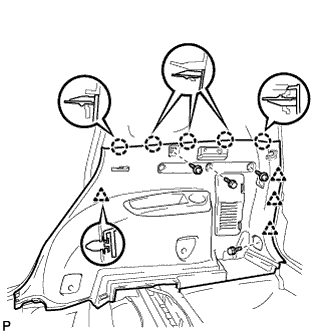
REMOVE DECK TRIM SIDE PANEL ASSEMBLY LH
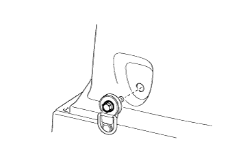
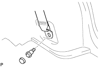
Disconnect the rear No.1 seat outer belt's floor anchor.
Remove the anchor cover.
Remove the bolt and disconnect the floor anchor.
Remove the 2 screws and 2 bolts.
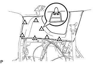
Using a screwdriver, detach the 5 claws.
HINT:
Tape the screwdriver tip before use.
Using a clip remover, detach the 4 clips and remove the trim board.
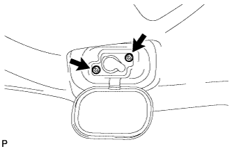
Disconnect the power outlet socket connector.
Remove the belt hanger.
40.
REMOVE DECK TRIM SIDE PANEL ASSEMBLY RH
Disconnect the rear No.1 seat outer belt's floor anchor.
Remove the anchor cover.
Remove the bolt and disconnect the floor anchor.
Remove the 2 screws and 2 bolts.
Using a screwdriver, detach the 5 claws.
HINT:
Tape the screwdriver tip before use.
Using a clip remover, detach the 4 clips and remove the trim board.
Remove the belt hanger.
41.
REMOVE INNER ROOF SIDE GARNISH ASSEMBLY LH
Using a clip remover, detach the 7 clips and remove the garnish.
42.
REMOVE INNER ROOF SIDE GARNISH ASSEMBLY RH
HINT:
Use the same procedures described for the LH side.
43.
REMOVE REAR ROOM PARTITION NET HOOK LH
Remove the 2 screws and net hook.
44.
REMOVE REAR ROOM PARTITION NET HOOK RH
HINT:
Use the same procedures described for the LH side.
45.
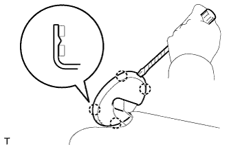
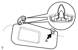
REMOVE VISOR ASSEMBLY LH
Using a screwdriver, detach the 4 claws and remove the visor bracket cover.
HINT:
Tape the screwdriver tip before use.
Remove portion A from the visor holder.
Detach the 2 claws and remove the visor.
46.
REMOVE VISOR ASSEMBLY RH
HINT:
Use the same procedures described for the LH side.
47.
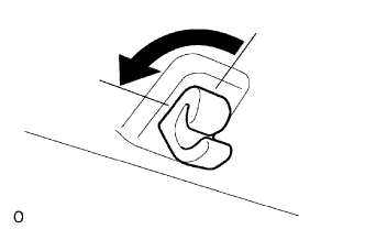
REMOVE VISOR HOLDER
Remove the visor holder by turning it counterclockwise.
48.
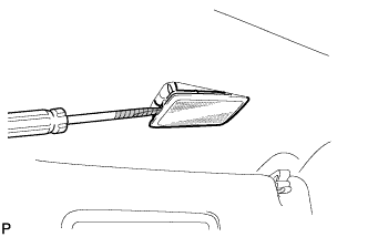
REMOVE VANITY LIGHT ASSEMBLY
Using a screwdriver, pry out the vanity light assembly.
HINT:
Tape the screwdriver tip before use.
Detach the 2 claws and vanity light.
49.
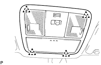
REMOVE MAP LIGHT ASSEMBLY
Detach the 4 clips and remove the map light.
Disconnect the light connector.
50.
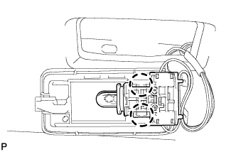
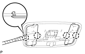
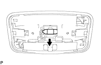
REMOVE ROOM LIGHT ASSEMBLY
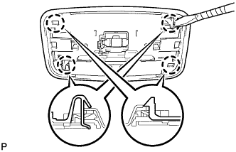
Using a screwdriver, detach the 4 claws and remove the 2 covers.
HINT:
Tape the screwdriver tip before use.
Remove the bulb from the room light switch base.
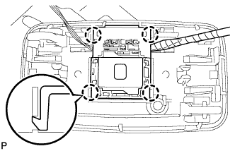
Using a screwdriver, detach the 4 claws and remove the light.
HINT:
Tape the screwdriver tip before use.
Using a screwdriver, detach the 4 claws and remove the room light switch base.
HINT:
Tape the screwdriver tip before use.
51.
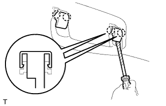
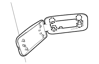
REMOVE ASSIST GRIP COVER (for Front Grip)
Using a screwdriver, detach the 4 claws and remove the 2 assist grip covers.
HINT:
Tape the screwdriver tip before use.
52.
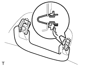
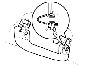
REMOVE ASSIST GRIP SUB-ASSEMBLY
Detach the 4 claws and remove the assist grip.
53.
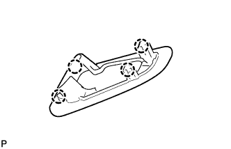
REMOVE ASSIST GRIP COVER (for Rear Grip)
Using a screwdriver, detach the 4 claws and remove the 2 assist grip covers.