TERMINALS OF ECU
System information · Vehicles built from Nov 2005
| CHECK INSTRUMENT PANEL JUNCTION BLOCK (MAIN BODY ECU) |
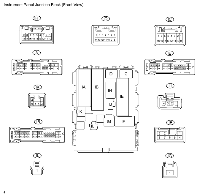

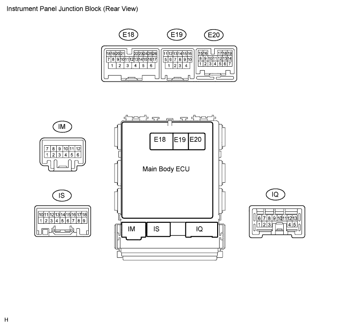
Measure the voltage of the connectors.
Symbols (Terminal No.)
Wiring Color
Terminal Description
Condition
Specified Condition
HRLY (E18-20) - GND (IE-17)
BR - W-B
HEAD Relay
(HEAD signal)
Light control switch is OFF or TAIL
10 to 14 V
HRLY (E18-20) - GND (IE-17)
BR - W-B
HEAD Relay
(HEAD signal)
Light control switch is HEAD
Below 1 V
DIM (E19-3) - GND (IE-17)
LG - W-B
DRL Relay
(High beam signal)
Light control switch is HEAD
Below 1 V
DIM (E19-3) - GND (IE-17)
LG - W-B
DRL Relay
(High beam signal)
Light control switch is HEAD
10 to 14 V
TAIL (E18-21) - GND (IE-17)
W - W-B
TAIL relay
(TAIL signal)
Light control switch is OFF
Below 1 V
TAIL (E18-21) - GND (IE-17)
W - W-B
TAIL relay
(TAIL signal)
Light control switch is TAIL
10 to 14 V
ILE (IK-2) - GND (IE-17)
W - W-B
Illumination signal
- Room light switch position is DOOR
- Door closed
10 to 14 V
ILE (IK-2) - GND (IE-17)
W - W-B
Illumination signal
- Room light switch position is DOOR
- Door open
Below 1 V
FSPT (E18-2) - GND (IE-17)
V - W-B
Foot light illumination
(Illumination signal)
Foot light illumination OFF
10 to 14 V
FSPT (E18-2) - GND (IE-17)
V - W-B
Foot light illumination
(Illumination signal)
Foot light illumination ON
Below 1 V
HU (IJ-4) - GND (IE-17)
O - W-B
Headlight dimmer switch
(HIGH signal)
Light control switch is HEAD
Headlight dimmer switch is LOW
10 to 14 V
HU (IJ-4) - GND (IE-17)
O - W-B
Headlight dimmer switch
(HIGH signal)
Light control switch is HEAD
Headlight dimmer switch is HIGH
Below 1 V
LCTY (E18-8) - GND (IE-17)
SB - W-B
Courtesy switch
(Rear left door circuit)
Rear left door is open
Below 1 V
LCTY (E18-8) - GND (IE-17)
SB - W-B
Courtesy switch
(Rear left door circuit)
Rear left door is open
10 to 14 V
DCTY (IA-21) - GND (IE-17)*1
DCTY (IC-6) - GND (IE-17)*2
W - W-B*1
BR - W-B*2
Courtesy switch
(Front driver side door circuit)
Front driver side door is open
Below 1 V
DCTY (IA-21) - GND (IE-17)*1
DCTY (IC-6) - GND (IE-17)*2
W - W-B*1
BR - W-B*2
Courtesy switch
(Front driver side door circuit)
Front driver side door is open
10 to 14 V
RRCY (ID-7) - GND (IE-17)
LG - W-B
Courtesy switch
(Rear right door circuit)
Rear right door is open
Below 1 V
RRCY (ID-7) - GND (IE-17)
LG - W-B
Courtesy switch
(Rear right door circuit)
Rear right door is closed
10 to 14 V
HF (E18-22) - GND (IE-17)
R - W-B
Headlight dimmer switch
(FLASH signal)
Headlight dimmer switch is OFF
10 to 14 V
HF (E18-22) - GND (IE-17)
R - W-B
Headlight dimmer switch
(FLASH signal)
Headlight dimmer switch is FLASH
Below 1 V
FFOG (E20-13) - GND (IE-17)
GR - W-B
Front fog light switch
(Front fog light signal)
Light control switch is TAIL
Front fog light switch is OFF
10 to 14 V
FFOG (E20-13) - GND (IE-17)
GR - W-B
Front fog light switch
(Front fog light signal)
Light control switch is TAIL
Front fog light switch is ON
Below 1 V
RFOG (E20-9) - GND (IE-17)
L - W-B
Rear fog light switch
(Rear fog light signal)
Light control switch is TAIL
Rear fog light switch is OFF
10 to 14 V
RFOG (E20-9) - GND (IE-17)
L - W-B
Rear fog light switch
(Rear fog light signal)
Light control switch is TAIL
Rear fog light switch is ON
Below 1 V
PCTY (IC-14) - GND (IE-17)
BR - W-B
Courtesy switch
(Front passenger side door circuit)
Front passenger side door is open
Below 1 V
PCTY (IC-14) - GND (IE-17)
BR - W-B
Courtesy switch
(Front passenger side door circuit)
Front passenger side door is open
10 to 14 V
BCTY (IA-7) - GND (IE-17)
LG - W-B
Courtesy switch
(Back door)
Back door is open
Below 1 V
BCTY (IA-7) - GND (IE-17)
LG - W-B
Courtesy switch
(Back door)
Back door is closed
10 to 14 V
LSWD (E18-25) - GND (IE-17)
Y - W-B
Door lock position switch
(Front driver side door)
Front driver side door is in unlock position
10 to 14 V
LSWD (E18-25) - GND (IE-17)
Y - W-B
Door lock position switch
(Front driver side door)
Front driver side door is in lock position
Below 1 V
- HINT:
- *1: for LHD
- *2: for RHD
- Room light switch position is DOOR