6.
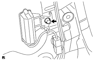
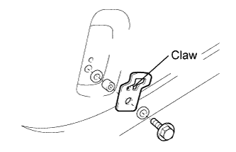
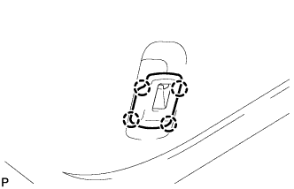
INSTALL RECLINING REMOTE CONTROL LEVER BEZEL LH
Attach the 6 claws to install the bezel.
7.
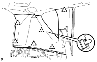
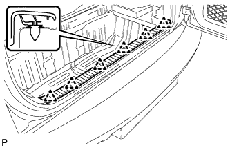
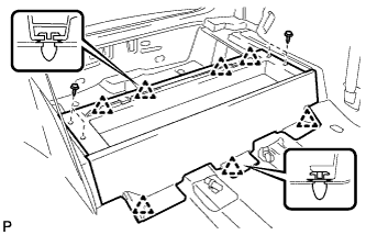
INSTALL REAR FLOOR FINISH PLATE
Attach the 6 clips to install the finish plate.
8.
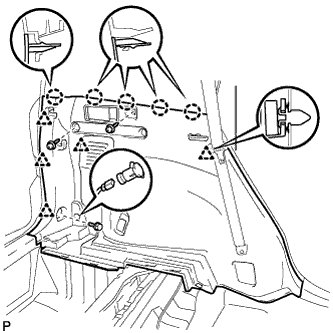
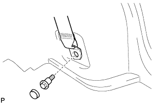
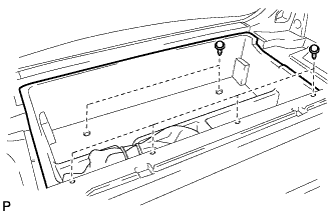
INSTALL REAR FLOOR NO. 1 MAT SUPPORT SIDE PLATE
Attach the 7 clips to install the side plate.
Install the 4 screws.
9.
INSTALL JACK CARRIER ASSEMBLY
Install the jack carrier with the 7 clips.
10.
INSTALL REAR FLOOR NO. 2 BOARD
11.
INSTALL REAR FLOOR NO. 3 BOARD
12.
INSTALL DECK BOARD ASSEMBLY
13.
INSTALL REAR FLOOR NO. 1 BOARD
14.
INSTALL TONNEAU COVER ASSEMBLY
15.
INSTALL PACKAGE TRAY TRIM POCKET SUB-ASSEMBLY
16.
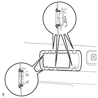
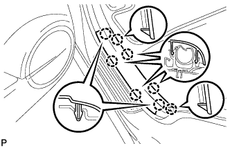
INSTALL REAR DOOR SCUFF PLATE LH
Attach the 8 claws to install the scuff plate.
17.
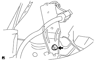
INSTALL TIRE PRESSURE WARNING ANTENNA FRONT RH
Install the antenna with the nut.
Torque:
7.5 N*m{
76 kgf*cm
, 66 in.*lbf
}
Connect the connector.
18.
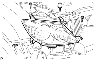
INSTALL HEADLIGHT ASSEMBLY RH
Install the 3 screws and bolt.
Connect the connectors and install the headlight.
19.
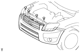
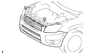
INSTALL FRONT BUMPER REINFORCEMENT SUB-ASSEMBLY UPPER
Install the reinforcement and install the 2 bolt.
Connect the 2 horns connectors.
20.
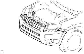
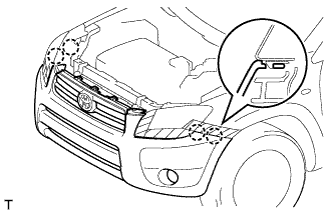
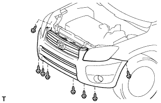
INSTALL FRONT BUMPER COVER
Put protective tape under the front fender and headlight.
Install the 4 clips.
Install the hood cushion center.
w/ Headlight Cleaner: Connect the headlight cleaner.
w/ Fog Light: Connect the 2 fog light connectors.
Attach the 4 claws to install the bumper cover.
Install the 8 screws.
21.
INSTALL RADIATOR SUPPORT OPENING COVER
Install the 2 clips.
22.
INSTALL FRONT FENDER LINER RH
HINT:
Use the same procedures described for the LH side.
23.
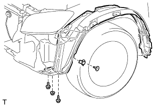
INSTALL FRONT FENDER LINER LH
Install the fender liner with the clip and fender liner retainer.
w/ Splash Shield: Install the front fender splash shield LH.
Install the screw, nut and bolt.
24.
CONNECT CABLE TO NEGATIVE BATTERY TERMINAL
25.
REGISTER TRANSMITTER ID
NOTICE:
It is necessary to register the transmitter ID in the tire pressure warning ECU and receiver when replacing the tire wheel and/or tire pressure warning ECU and receiver.
Prepare all of the transmitter ID data before starting registration.
HINT:
Read the registered transmitter IDs that are stored in the ECU using the intelligent tester and make a note of them.
If reading stored transmitter IDs is impossible due to malfunctions of components such as the tire pressure warning antenna and receiver, replace the tire wheel.
When replacing the tire wheel, wriee down the IDs from the sticker on the inside surface of the tire wheel.
Connect the intelligent tester to the DLC3.
Turn the ignition switch on (IG).
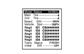
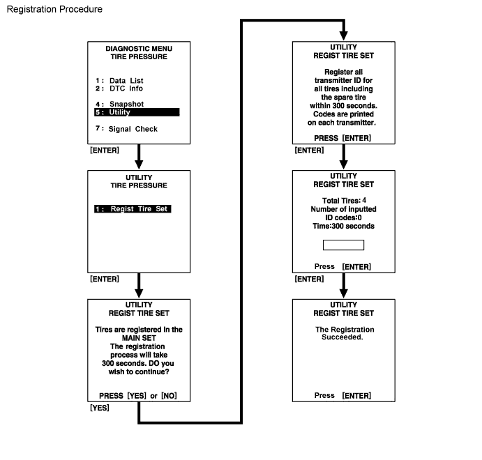
*1: Read and write down the ID (ID1 to ID4) by using the Data List.
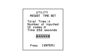
*2: Select REGIST TIRE SET following the intelligent tester screen (UTILITY - REGIST TIRE SET).
*3: Select the registration mode "MAIN".
Input the ID (ID1 to ID4) using the intelligent tester and transmit it to the tire pressure warning ECU and receiver.
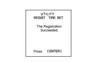
Set the ID transmission condition to "ID Registration is complete".
HINT:
The previously registered IDs will be deleted from the memory when the registration is completed.
If the operations of *1 to *3 are not completed within 5 minutes, the mode will return to normal operation mode.