Open in One Side of CAN Branch Line
Circuit diagnosis · Vehicles built Nov 2005 – Jul 2008
Versions by build date: Nov 2005 – Jul 2008 from Aug 2008
DESCRIPTION
If 2 or more ECUs and/or sensors do not appear on the intelligent tester's "BUS CHECK" screen via the CAN VIM, one side of the CAN branch wire may be open. (One side of the CANH [branch wire] /CANL [branch wire] of the ECU and/or sensor is open.)| Symptom |
Trouble Area |
| 2 or more ECUs and/or sensors do not appear on intelligent tester "BUS CHECK" screen via CAN VIM. |
|
- HINT:
- *1: w/ ABS
- *2: w/ VSC
- *3: for 4WD
- *4: for 2WD with VSC and 4WD
WIRING DIAGRAM
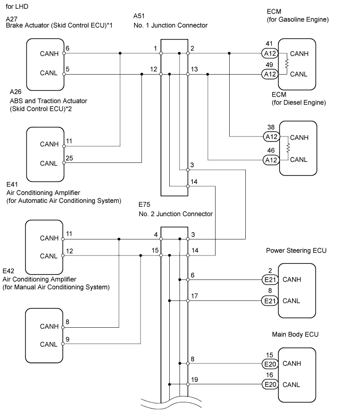

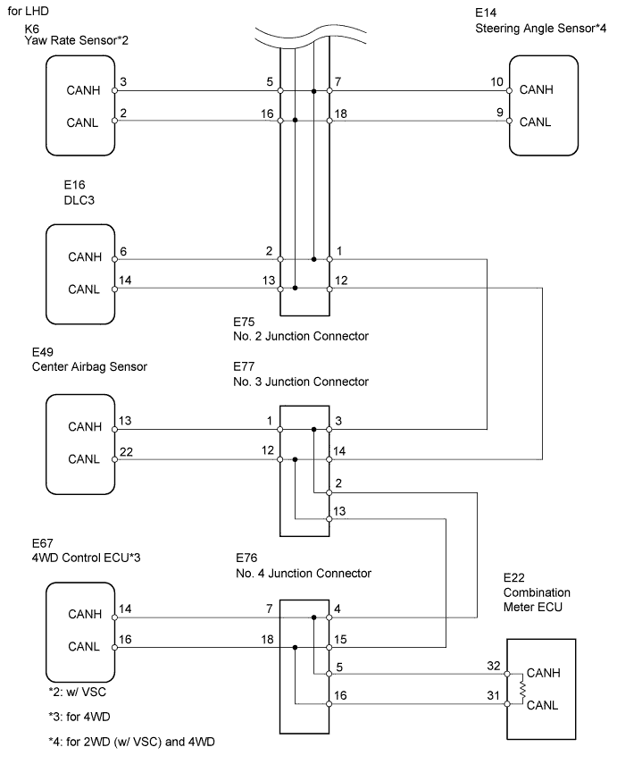
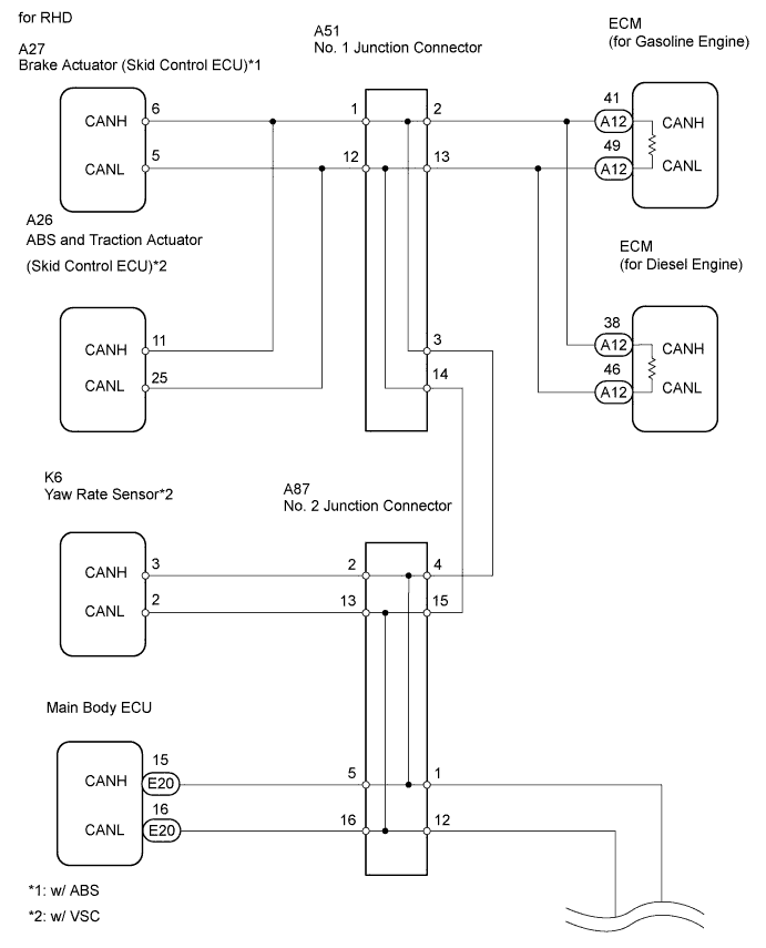
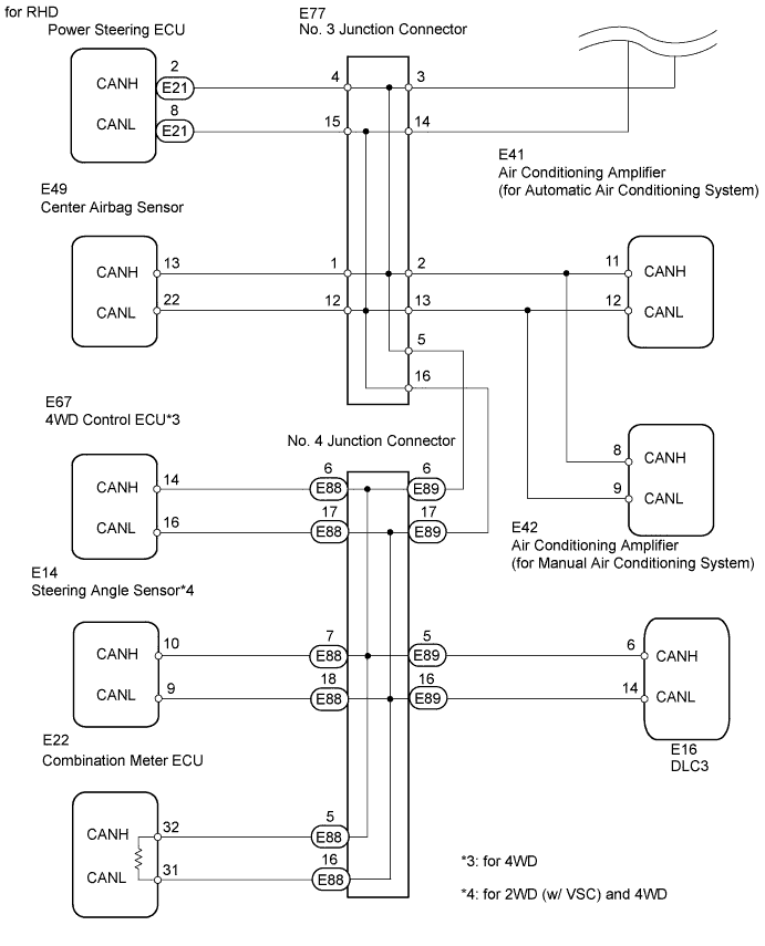
INSPECTION PROCEDURE
- NOTICE:
- Turn the ignition switch off before measuring the resistances of the main wire and the branch wire.
- For Auto:
After the ignition switch is turned off, check that the key reminder warning system is not in operation.
- For Reminder:
After the ignition switch is turned off, check that the key reminder warning system and light reminder buzzer are not in operation.
- Before measuring the resistance, leave the vehicle for at least 1 minute and do not operate the ignition switch, any switches or doors. If doors need to be opened in order to check connectors, open the doors and leave them open.
- Turn the ignition switch off before measuring the resistances of the main wire and the branch wire.
- HINT:
- Perform the following inspection for the ECUs (sensors) which are not displayed on the intelligent tester. If a malfunction cannot be identified, perform the following inspections for the ECUs (sensors) connected to the CAN communication system.
- Perform the following inspection for the ECUs (sensors) which are not displayed on the intelligent tester. If a malfunction cannot be identified, perform the following inspections for the ECUs (sensors) connected to the CAN communication system.
- Do not remove the combination meter and ECM, as they are the end parts of the circuit. If removed, CAN communication will not be possible.
- Do not remove the combination meter and ECM, as they are the end parts of the circuit. If removed, CAN communication will not be possible.
- The open circuit confirmation of the combination meter, ECM and main wire is performed in the CHECK CAN BUS LINE procedure of HOW TO PROCEED WITH TROUBLESHOOTING. This inspection only has procedures for checking for an open circuit on one side of the CAN branch wire.
- The open circuit confirmation of the combination meter, ECM and main wire is performed in the CHECK CAN BUS LINE procedure of HOW TO PROCEED WITH TROUBLESHOOTING. This inspection only has procedures for checking for an open circuit on one side of the CAN branch wire.
| 1. CHECK FOR OPEN IN ONE SIDE OF BRANCH WIRE (BRAKE ACTUATOR) |

- NOTICE:
- For vehicles without ABS, go to "CHECK FOR OPEN IN ONE SIDE OF BRANCH WIRE (ABS AND TRACTION ACTUATOR)".
Disconnect the A27 brake actuator (skid control ECU) connector.
Select "BUS CHECK" on the intelligent tester display via the CAN VIM (Click here).
Result Result
Proceed to
ABS/VSC/TRC not displayed on intelligent tester.
A
Several ECUs and sensors other than ABS/VSC/TRC not displayed on intelligent tester.
B
|
|
||||

| A | |
 |
| 2. CHECK FOR OPEN IN ONE SIDE OF BRANCH WIRE (BRAKE ACTUATOR BRANCH WIRE) |
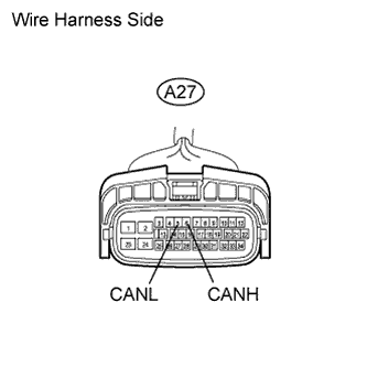 |
Measure the resistance of the wire harness side connector.
- Standard resistance:
- 54 to 69 Ω
|
|
||||

| OK | ||
 |
||
| ||
| 3. CHECK FOR OPEN IN ONE SIDE OF BRANCH WIRE (ABS AND TRACTION ACTUATOR) |
- NOTICE:
- For vehicles without VSC, go to "CHECK FOR OPEN IN ONE SIDE OF BRANCH WIRE (STEERING ANGLE SENSOR)".
Disconnect the A26 ABS and traction actuator (skid control ECU) connector.
Select "BUS CHECK" on the intelligent tester display via the CAN VIM (Click here).
Result Result
Proceed to
ABS/VSC/TRC not displayed on intelligent tester.
A
Several ECUs and sensors other than ABS/VSC/TRC not displayed on intelligent tester.
B
|
|
||||
| A | |
|
| 4. CHECK FOR OPEN IN ONE SIDE OF BRANCH WIRE (ABS AND TRACTION ACTUATOR BRANCH WIRE) |
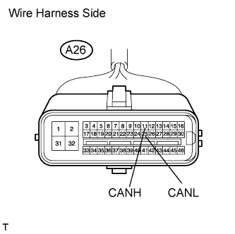 |
Measure the resistance of the wire harness side connector.
- Standard resistance:
- 54 to 69 Ω
|
|
||||
| OK | ||
|
||
| ||
| 5. CHECK FOR OPEN IN ONE SIDE OF BRANCH WIRE (YAW RATE SENSOR) |
- NOTICE:
- For vehicles without VSC, go to "CHECK FOR OPEN IN ONE SIDE OF BRANCH WIRE (STEERING ANGLE SENSOR)".
Disconnect the K6 yaw rate sensor connector.
Select "BUS CHECK" on the intelligent tester display via the CAN VIM (Click here).
Result Result
Proceed to
Yaw Rate / Deceleration Sensor not displayed on intelligent tester.
A
Several ECUs and sensors other than Yaw Rate / Deceleration Sensor not displayed on intelligent tester.
B
|
|
||||
| A | |
|
| 6. CHECK FOR OPEN IN ONE SIDE OF BRANCH WIRE (YAW RATE SENSOR BRANCH WIRE) |
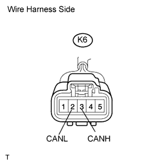 |
Measure the resistance of the wire harness side connector.
- Standard resistance:
- 54 to 69 Ω
|
|
||||
| OK | ||
|
||
| ||
| 7. CHECK FOR OPEN IN ONE SIDE OF BRANCH WIRE (STEERING ANGLE SENSOR) |
- NOTICE:
- For vehicles without 2WD with VSC and 4WD, go to "CHECK FOR OPEN IN ONE SIDE OF BRANCH WIRE (POWER STEERING ECU)".
Disconnect the E14 steering angle sensor connector.
Select "BUS CHECK" on the intelligent tester display via the CAN VIM (Click here).
Result Result
Proceed to
Steering Angle Sensor not displayed on intelligent tester.
A
Several ECUs and sensors other than Steering Angle Sensor not displayed on intelligent tester.
B
|
|
||||
| A | |
|
| 8. CHECK FOR OPEN IN ONE SIDE OF BRANCH WIRE (STEERING ANGLE SENSOR BRANCH WIRE) |
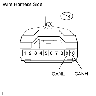 |
Measure the resistance of the wire harness side connector.
- Standard resistance:
- 54 to 69 Ω
|
|
||||
| OK | ||
|
||
| ||
| 9. CHECK FOR OPEN IN ONE SIDE OF BRANCH WIRE (POWER STEERING ECU) |
Disconnect the E21 power steering ECU connector.
Select "BUS CHECK" on the intelligent tester display via the CAN VIM (Click here).
Result Result
Proceed to
EPS not displayed on intelligent tester.
A
Several ECUs and sensors other than EPS not displayed on intelligent tester.
B
|
|
||||
| A | |
|
| 10. CHECK FOR OPEN IN ONE SIDE OF BRANCH WIRE (POWER STEERING ECU BRANCH WIRE) |
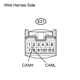 |
Measure the resistance of the wire harness side connector.
- Standard resistance:
- 54 to 69 Ω
|
|
||||
| OK | ||
|
||
| ||
| 11. CHECK FOR OPEN IN ONE SIDE OF BRANCH WIRE (MAIN BODY ECU) |
Disconnect the E20 main body ECU connector.
Select "BUS CHECK" on the intelligent tester display via the CAN VIM (Click here).
Result Result
Proceed to
Integrated J/B not displayed on intelligent tester.
A
Several ECUs and sensors other than Integrated J/B not displayed on intelligent tester.
B
|
|
||||
| A | |
|
| 12. CHECK FOR OPEN IN ONE SIDE OF BRANCH WIRE (MAIN BODY ECU BRANCH WIRE) |
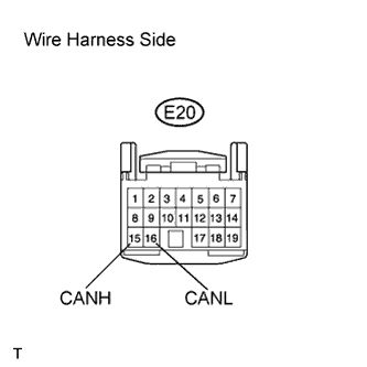 |
Measure the resistance of the wire harness side connector.
- Standard resistance:
- 54 to 69 Ω
|
|
||||
| OK | ||
|
||
| ||
| 13. CHECK FOR OPEN IN ONE SIDE OF BRANCH WIRE (AIR CONDITIONING AMPLIFIER) |
Disconnect the E41*1 or E42*2 air conditioning amplifier connector.
- HINT:
- *1: for Automatic air conditioning system.
- *2: for Manual air conditioning system.
- *1: for Automatic air conditioning system.
Select "BUS CHECK" on the intelligent tester display via the CAN VIM (Click here).
Result Result
Proceed to
Air Conditioner not displayed on intelligent tester.
A
Several ECUs and sensors other than Air Conditioner not displayed on intelligent tester.
B
|
|
||||
| A | |
|
| 14. CHECK FOR OPEN IN ONE SIDE OF BRANCH WIRE (AIR CONDITIONING AMPLIFIER BRANCH WIRE) |
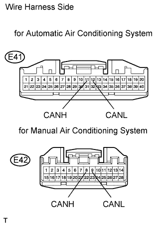 |
Measure the resistance of the wire harness side connector.
- Standard resistance:
- 54 to 69 Ω
|
|
||||
| OK | ||
|
||
| ||
| 15. CHECK FOR OPEN IN ONE SIDE OF BRANCH WIRE (4WD CONTROL ECU) |
- NOTICE:
- For vehicles without 4WD, go to "CHECK FOR OPEN IN ONE SIDE OF BRANCH WIRE (CENTER AIRBAG SENSOR ASSEMBLY)".
Disconnect the E67 4WD control ECU connector.
Select "BUS CHECK" on the intelligent tester display via the CAN VIM (Click here).
Result Result
Proceed to
Four Wheel Drive Control not displayed on intelligent tester.
A
Several ECUs and sensors other than Four Wheel Drive Control not displayed on intelligent tester.
B
|
|
||||
| A | |
|
| 16. CHECK FOR OPEN IN ONE SIDE OF BRANCH WIRE (4WD CONTROL ECU BRANCH WIRE) |
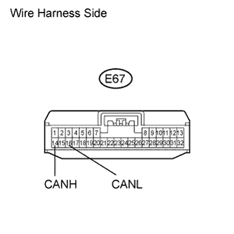 |
Measure the resistance of the wire harness side connector.
- Standard resistance:
- 54 to 69 Ω
|
|
||||
| OK | ||
|
||
| ||
| 17. CHECK FOR OPEN IN ONE SIDE OF BRANCH WIRE (CENTER AIRBAG SENSOR ASSEMBLY BRANCH WIRE) |
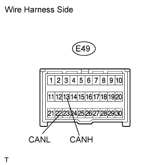 |
Disconnect the E49 center airbag sensor connector.
Measure the resistance of the wire harness side connector.
- Standard resistance:
- 54 to 69 Ω
|
|
||||
| OK | ||
|
||
| ||