CAN Main Wire for Disconnection (RHD Models)
Circuit diagnosis · Vehicles built from Nov 2005
DESCRIPTION
There may be an open circuit in the CAN main wire and/or the DLC3 branch wire when the resistance between terminals 6 (CANH) and 14 (CANL) of the DLC3 is 69 Ω or more.| Symptom |
Trouble Area |
| Resistance between terminals 6 (CANH) and 14 (CANL) of DLC3 is 69 Ω or more. |
|
WIRING DIAGRAM
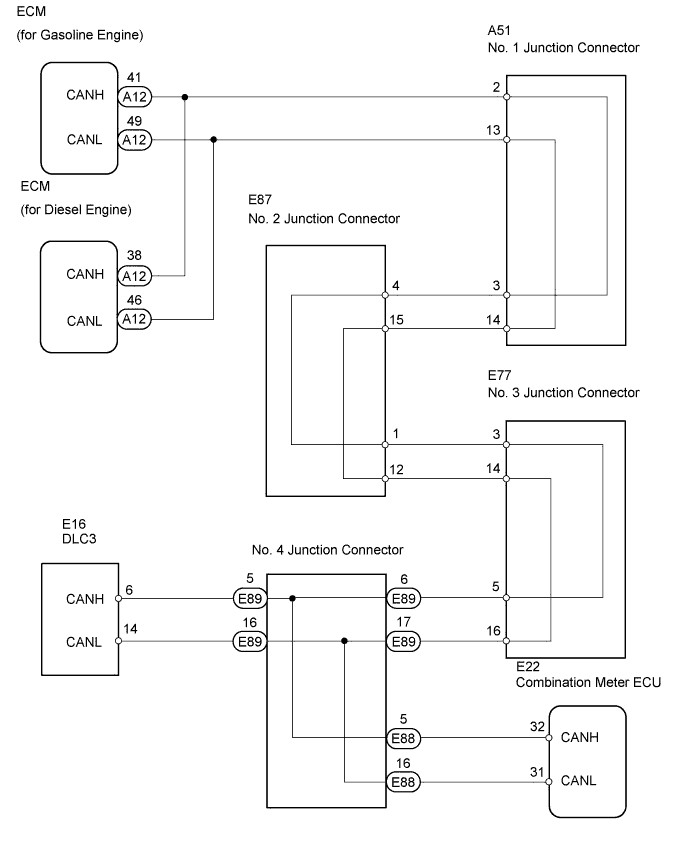

INSPECTION PROCEDURE
- NOTICE:
- Turn the ignition switch off before measuring the resistances of the main wire and the branch wire.
- For Auto:
After the ignition switch is turned off, check that the key reminder warning system is not in operation.
- For Reminder:
After the ignition switch is turned off, check that the key reminder warning system and light reminder buzzer are not in operation.
- Before measuring the resistance, leave the vehicle for at least 1 minute and do not operate the ignition switch, any switches or doors. If doors need to be opened in order to check connectors, open the doors and leave them open.
- Turn the ignition switch off before measuring the resistances of the main wire and the branch wire.
- HINT:
- Operating the ignition switch, any switches or any doors triggers related ECU and sensor communication with the CAN, which causes resistance variation.
| 1. CHECK DLC3 |

Measure the resistance of the DLC3.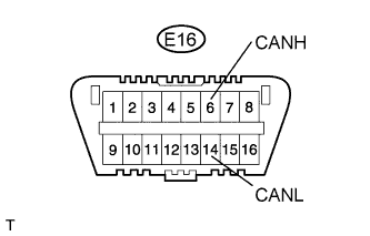
- Standard resistance:
Tester Connection
Condition
Specified Condition
Proceed to
E16-6 (CANH) - E16-14 (CANL)
Ignition switch off
108 to 132 Ω
A
E16-6 (CANH) - E16-14 (CANL)
Ignition switch off
132 Ω or more
B
- NOTICE:
- When the measured value is 132 Ω or more and a CAN communication system diagnostic trouble code is output, there may be a fault besides disconnection of the DLC3 branch wire. For that reason, troubleshooting should be performed again from "HOW TO PROCEED WITH TROUBLESHOOTING" (Click here) after repairing the trouble area.
|
|
||||

| A | |
 |
| 2. CHECK CAN MAIN WIRE FOR DISCONNECTION (NO. 2 JUNCTION CONNECTOR - ECM) |
Disconnect the E87 No. 2 junction connector.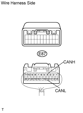
Measure the resistance of the wire harness side connector.
- Standard resistance:
Tester Connection
Condition
Specified Condition
E87-4 (CANH) - E87-15 (CANL)
Ignition switch off
108 to 132 Ω
|
|
||||

| OK | |
|
| 3. CHECK CAN MAIN WIRE FOR DISCONNECTION (NO. 2 JUNCTION CONNECTOR - COMBINATION METER ECU) |
Measure the resistance of the wire harness side connector.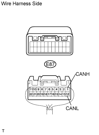
- Standard resistance:
Tester Connection
Condition
Specified Condition
E87-1 (CANH) - E87-12 (CANL)
Ignition switch off
108 to 132 Ω
|
|
||||
| OK | ||
 |
||
| ||
| 4. CONNECT CONNECTOR |
Reconnect the E87 No. 2 junction connector.
| NEXT | |
|
| 5. CHECK CAN MAIN WIRE FOR DISCONNECTION (NO. 1 JUNCTION CONNECTOR - ECM) |
Disconnect the A51 No. 1 junction connector.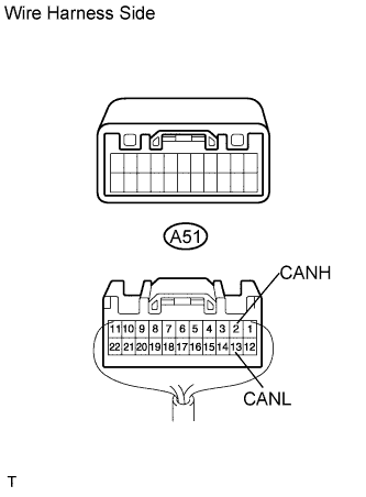
Measure the resistance of the wire harness side connector.
- Standard resistance:
Tester Connection
Condition
Specified Condition
A51-2 (CANH) - A51-13 (CANL)
Ignition switch off
108 to 132 Ω
|
|
||||
| OK | |
|
| 6. CHECK CAN MAIN WIRE FOR DISCONNECTION (NO. 1 JUNCTION CONNECTOR - NO. 2 JUNCTION CONNECTOR) |
Measure the resistance of the wire harness side connector.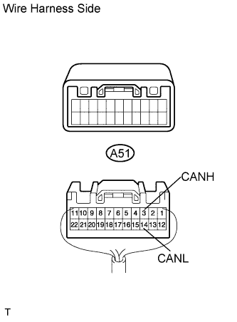
- Standard resistance:
Tester Connection
Condition
Specified Condition
A51-3 (CANH) - A51-14 (CANL)
Ignition switch off
108 to 132 Ω
|
|
||||
| OK | ||
|
||
| ||
| 7. CONNECT CONNECTOR |
Reconnect the A51 No. 1 junction connector.
| NEXT | |
|
| 8. CHECK CAN MAIN WIRE FOR DISCONNECTION (ECM - NO. 1 JUNCTION CONNECTOR) |
Disconnect the A12 ECM connector.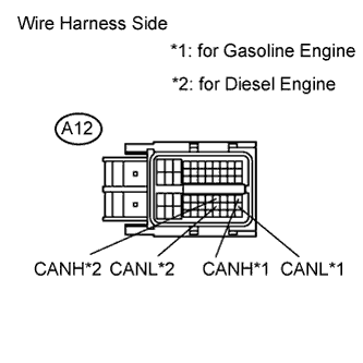
Measure the resistance of the wire harness side connector.
- Standard resistance:
- for Gasoline Engine:
Tester Connection
Condition
Specified Condition
A12-41 (CANH) - A12-49 (CANL)
Ignition switch off
108 to 132 Ω
- for Diesel Engine:
Tester Connection
Condition
Specified Condition
A12-38 (CANH) - A12-46 (CANL)
Ignition switch off
108 to 132 Ω
|
|
||||
| OK | ||
|
||
| ||
| 9. CONNECT CONNECTOR |
Reconnect the E87 No. 2 junction connector.
| NEXT | |
|
| 10. CHECK CAN MAIN WIRE FOR DISCONNECTION (NO. 4 JUNCTION CONNECTOR - NO. 2 JUNCTION CONNECTOR) |
Disconnect the E89 No. 4 junction connector.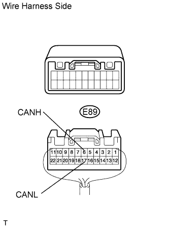
Measure the resistance of the wire harness side connector.
- Standard resistance:
Tester Connection
Condition
Specified Condition
E89-6 (CANH) - E89-17 (CANL)
Ignition switch off
108 to 132 Ω
|
|
||||
| OK | |
|
| 11. CHECK CAN MAIN WIRE FOR DISCONNECTION (NO. 4 JUNCTION CONNECTOR - COMBINATION METER ECU) |
Reconnect the E89 No. 4 junction connector.
Disconnect the E88 No. 4 junction connector.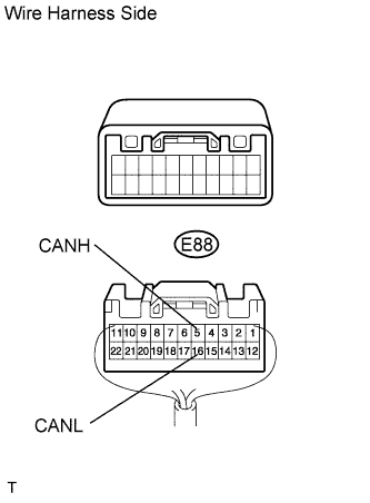
Measure the resistance of the wire harness side connector.
- Standard resistance:
Tester Connection
Condition
Specified Condition
E88-5 (CANH) - E88-16 (CANL)
Ignition switch off
108 to 132 Ω
|
|
||||
| OK | ||
|
||
| ||
| 12. CONNECT CONNECTOR |
Reconnect the E88 No. 4 junction connector.
| NEXT | |
|
| 13. CHECK CAN MAIN WIRE FOR DISCONNECTION (COMBINATION METER ECU - NO. 4 JUNCTION CONNECTOR) |
Disconnect the E22 combination meter ECU connector.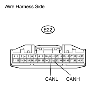
Measure the resistance of the wire harness side connector.
- Standard resistance:
Tester Connection
Condition
Specified Condition
E22-32 (CANH) - E22-31 (CANL)
Ignition switch off
108 to 132 Ω
|
|
||||
| OK | ||
|
||
| ||
| 14. CONNECT CONNECTOR |
Reconnect the A89 No. 4 junction connector.
| NEXT | |
|
| 15. CHECK CAN MAIN WIRE FOR DISCONNECTION (NO. 2 JUNCTION CONNECTOR - NO. 3 JUNCTION CONNECTOR) |
Disconnect the E77 No. 3 junction connector.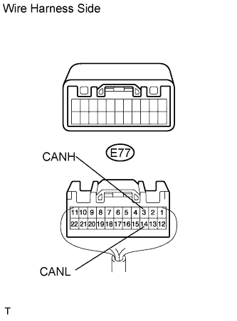
Measure the resistance of the wire harness side connector.
- Standard resistance:
Tester Connection
Condition
Specified Condition
E77-3 (CANH) - E77-14 (CANL)
Ignition switch off
108 to 132 Ω
|
|
||||
| OK | |
|
| 16. CHECK CAN MAIN WIRE FOR DISCONNECTION (NO. 3 JUNCTION CONNECTOR - NO. 4 JUNCTION CONNECTOR) |
Measure the resistance of the wire harness side connector.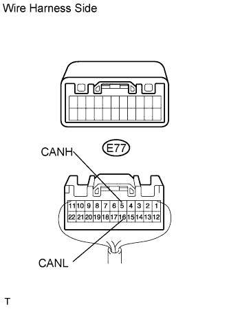
- Standard resistance:
Tester Connection
Condition
Specified Condition
E77-5 (CANH) - E77-16 (CANL)
Ignition switch off
108 to 132 Ω
|
|
||||
| OK | ||
|
||
| ||