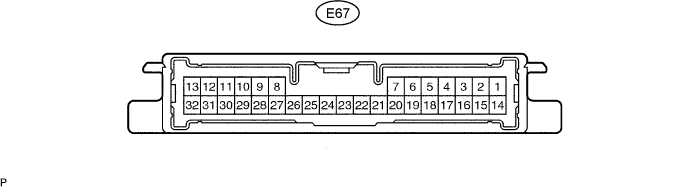
Symbols (Terminal No.)
|
Wiring Color
|
Terminal Description
|
Condition
|
Specified Condition
|
CANH (E67-14) - CANL (E67-16)
|
P - W
|
CAN communication
|
Ignition switch off
|
54 to 67 Ω
|
GND (E67-23) - Body ground
|
W-B - Body ground
|
Ground
|
Always
|
Below 1 Ω
|
4WDL (E67-7) - Body ground
|
R - W-B
|
Ground
|
Press continuously 4WD lock mode switch
|
Below 1 Ω
|
IG1 (E67-11) - GND (E67-23)
|
L - W-B
|
Power source voltage
|
Ignition switch on (IG)
|
10 to 14 V
|
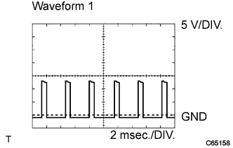
SLC+ (E67-13) - SLC- (E67-32)
|
W - B
|
4WD linear solenoid signal
|
Ignition switch on (IG)
|
Pulse generation (See waveform 1)
|
BSLC (E67-9) - GND (E67-23)
|
R - W-B
|
Power source voltage
|
Ignition switch on (IG)
|
10 to 14 V
|