C1241/94 Low Power Supply Voltage
Diagnostic trouble codes · Vehicles built Jan 2007 – Jul 2007
Versions by build date: Nov 2005 – Dec 2006 Jan 2007 – Jul 2007 from Aug 2007
DESCRIPTION
If a malfunction in the power source circuit occurs, or a malfunction in communication with the skid control ECU or in a speed sensor occurs, the 4WD control ECU will prohibit operations by the fail-safe function.| DTC No. |
DTC Detection Condition |
Trouble Area |
| C1241/94 |
When one of following conditions is met:
|
|
WIRING DIAGRAM
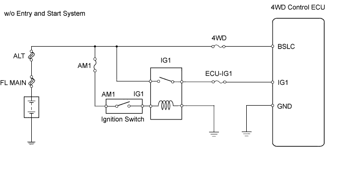

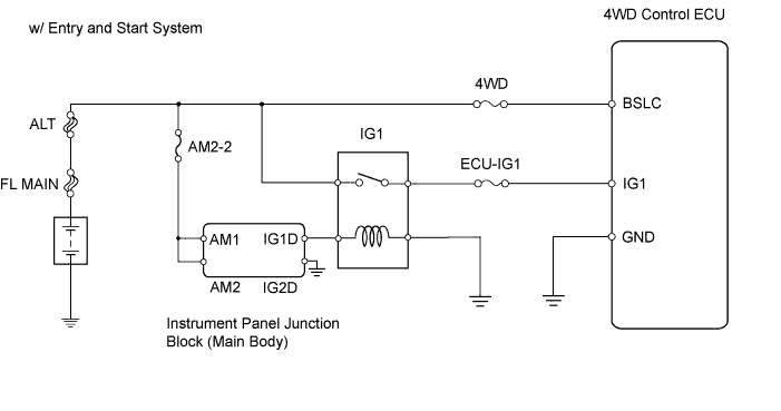
INSPECTION PROCEDURE
- HINT:
- Check the condition of each related circuit connector before troubleshooting (Click here).
| 1. CHECK FOR DTC |

Clear the DTC (Click here).
Turn the ignition switch on (IG) and check that no CAN communication system DTC is output.
Start the engine.
Drive the vehicle, accelerate to a speed of 3 km/h (2 mph) or more, and check that no speed sensor DTC (brake control system DTC) is output (Click here and Click here).
- Result:
Result
Proceed to
Neither CAN communication system DTC nor speed sensor DTC (Brake control system DTC) is output
A
CAN communication system DTC is output
B
Speed sensor DTC (Brake control system DTC) is output
C
- HINT:
- When DTCs indicating a CAN communication system malfunction are output, repair the CAN communication system before repairing each corresponding sensor.
|
|
||||
|
|
||||

| A | |
 |
| 2. INSPECT FUSE (ECU-IG1) |
Remove the ECU-IG1 fuse from the instrument junction block.
Measure the resistance of the fuse.
- Standard resistance:
- Below 1Ω
- HINT:
- Check for short circuits in all harnesses and connector connected to the ECU-IG1 fuse (Click here).
|
|
||||
| OK | |
|
| 3. CHECK WIRE HARNESS (4WD CONTROL ECU - BATTERY) |
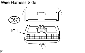 |
Disconnect the E 67 ECU connector.
Measure the voltage of the wire harness side connector.
- Standard voltage:
Tester Connection
Condition
Specified Condition
E67-11 (IG1) - Body ground
Ignition switch on (IG)
10 to 14 V
|
|
||||
| OK | |
|
| 4. CHECK WIRE HARNESS (4WD CONTROL ECU - BODY GROUND) |
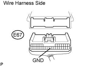 |
Disconnect the E67 ECU connector.
Measure the resistance of the wire harness side connector.
- Standard resistance:
Tester Connection
Specified Condition
E67-23 (GND) - Body ground
Below 1 Ω
|
|
||||
| OK | |
|
| 5. RECONFIRM DTC |
Clear the DTC (Click here).
Start the engine.
Drive the vehicle, accelerate to a speed of 3 km/h (2 mph) or more, and check if the same DTC is output.
- Result:
Result
Proceed to
DTC is output
A
DTC is not output
B
- HINT:
- Reinstall the sensor, connectors, etc. and restore the vehicle to its prior condition before rechecking DTCs.
|
|
||||
| A | ||
 |
||
| ||