DISASSEMBLY
Removal / installation · Vehicles built from Nov 2005
| 1. REMOVE CLUTCH RELEASE FORK SUB-ASSEMBLY |

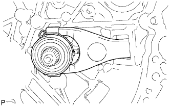  |
Remove the clutch release fork with the clutch release bearing from the transaxle case.
| 2. REMOVE CLUTCH RELEASE BEARING ASSEMBLY |
Remove the release bearing and clutch release bearing hub clip from the clutch release fork.
| 3. REMOVE CLUTCH RELEASE FORK SUPPORT |
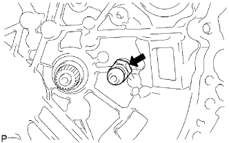 |
Remove the clutch release fork support from the transaxle case.
| 4. REMOVE CLUTCH RELEASE FORK BOOT |
Remove the clutch release fork boot from the transaxle case.
| 5. REMOVE SPEEDOMETER DRIVEN HOLE COVER SUB-ASSEMBLY |
Remove the bolt and hole cover.
Remove the O-ring from the hole cover.
| 6. REMOVE SELECTING BELLCRANK ASSEMBLY |
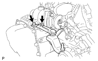 |
Remove the 2 bolts and selecting bellcrank from the transaxle case.
Remove the shift and select lever bush from the selecting bellcrank.
| 7. REMOVE CONTROL SHIFT LEVER |
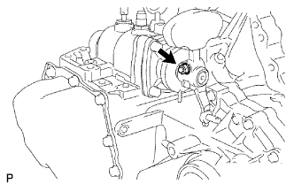 |
Remove the nut and spring washer.
Using a brass bar and hammer, tap out the shift outer lever lever lock pin.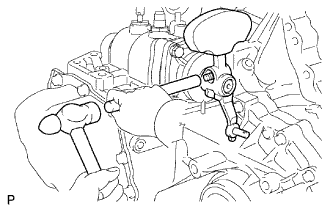
Remove the control shift lever.
| 8. REMOVE CONTROL SHAFT COVER |
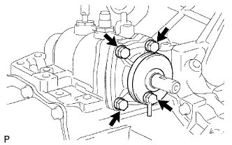 |
Remove the 4 bolts, control shift cover and gasket from the transaxle case.
| 9. FIX MANUAL TRANSAXLE ASSEMBLY |
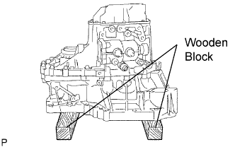 |
Place the transaxle on wooden blocks.
| 10. REMOVE NO. 1 LOCK BALL ASSEMBLY |
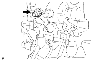 |
Remove the lock ball from the transaxle case.
| 11. REMOVE MANUAL TRANSAXLE BREATHER PLUG |
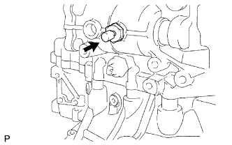 |
Remove the breather plug and gasket.
| 12. REMOVE SHIFT AND SELECT LEVER SHAFT ASSEMBLY |
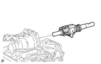 |
Remove the shift and select lever shaft from the transaxle case.
| 13. REMOVE BACK-UP LIGHT SWITCH ASSEMBLY |
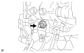 |
Remove the back-up light switch and gasket from the transaxle case.
| 14. REMOVE FILLER PLUG |
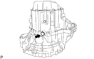 |
Remove the filler plug and gasket from the transaxle case.
| 15. REMOVE DRAIN PLUG SUB-ASSEMBLY |
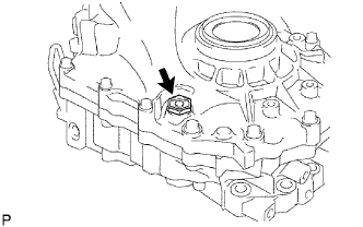 |
Remove the drain plug and gasket from the transaxle case.
| 16. REMOVE MANUAL TRANSAXLE CASE COVER SUB-ASSEMBLY |
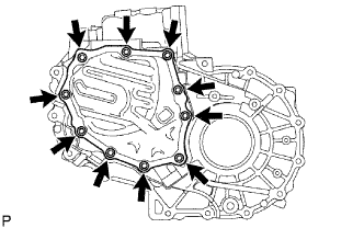 |
Remove the 10 bolts and transaxle case cover from the transaxle case.
| 17. REMOVE REAR MANUAL TRANSAXLE OUTPUT SHAFT SET NUT |
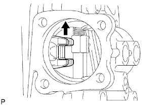 |
Engage the 2 gears simultaneously to lock the transaxle.
Using SST and a hammer, unstake the rear set nut.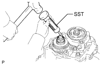
- SST
- 09930-00010
Using SST, remove the shaft rear set nut from the output shaft.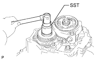
- SST
- 09229-55010
Disengage the 2 gears.
| 18. INSPECT 5TH GEAR THRUST CLEARANCE |
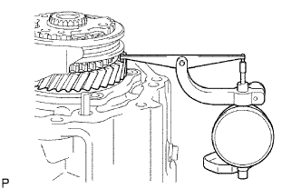 |
Using a dial indicator, measure the thrust clearance.
- Standard clearance:
- 0.10 to 0.65 mm (0.0039 to 0.0256 in.)
| 19. INSPECT 5TH GEAR RADIAL CLEARANCE |
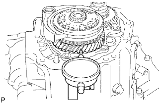 |
Using a dial indicator, measure the radial clearance.
- Standard clearance:
- 0.009 to 0.050 mm (0.0004 to 0.0020 in.)
| 20. REMOVE NO. 3 TRANSAXLE CLUTCH HUB |
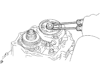 |
Using 2 screwdrivers and a hammer, tap out the No. 3 transaxle clutch hub shaft snap ring from the input shaft.
- HINT:
- Cover with a shop rag to keep the snap ring from flying off.
Remove the shift fork set bolt from the No. 3 gear shift fork.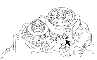
Using SST, remove the No. 3 transaxle clutch hub, No. 3 transaxle hub sleeve and No. 3 gear shift fork from the input shaft.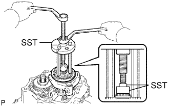
- SST
- 09950-30012
(09951-03010, 09953-03010, 09954-03010)
09950-50013 (09957-04010)
09950-60010 (09951-00280)
| 21. REMOVE 5TH GEAR |
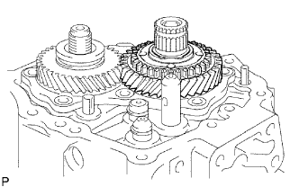 |
Remove the 5th gear from the input shaft.
| 22. REMOVE 5TH GEAR NEEDLE ROLLER BEARING |
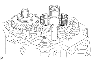 |
Remove the needle roller bearing from the input shaft.
| 23. REMOVE 5TH DRIVEN GEAR |
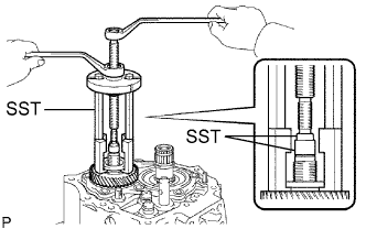 |
Using SST, remove the 5th driven gear from the output shaft.
- SST
- 09950-30012
(09951-03010, 09953-03010, 09954-03010, 09957-04010)
09950-60010 (09951-00180, 09955-03011)
09950-50013
| 24. REMOVE REAR BEARING RETAINER |
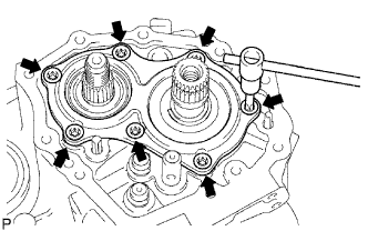 |
Using a T45 "torx" socket, remove the 7 "torx" screws and bearing retainer from the transaxle case.
| 25. REMOVE OUTPUT SHAFT REAR BEARING SHIM |
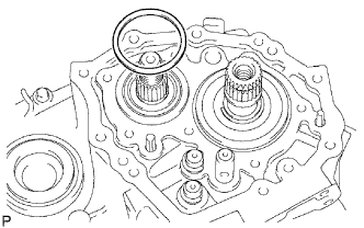 |
Remove the rear bearing shim from the output shaft.
| 26. REMOVE INPUT SHAFT REAR BEARING SHAFT SNAP RING |
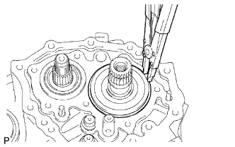 |
Using a snap ring expander, remove the shaft snap ring from the input shaft.
| 27. REMOVE SHIFT FORK SHAFT SHAFT SNAP RING |
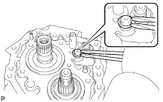 |
Using 2 screwdrivers and a hammer, tap out the shaft snap ring from the No. 1 gear shift fork shaft.
- HINT:
- Cover with a shop rag to keep the snap ring from flying off.
Using 2 screwdrivers and a hammer, tap out the shaft snap ring from the No. 2 gear shift fork shaft.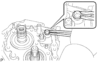
- HINT:
- Cover with a shop rag to keep the snap ring from flying off.
| 28. REMOVE REVERSE IDLER GEAR SHAFT BOLT |
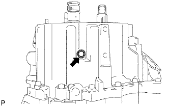 |
Remove the reverse idler gear shaft bolt and gasket.
| 29. REMOVE CLUTCH TUBE BRACKET |
Remove the bolt and clutch tube bracket.
| 30. REMOVE MANUAL TRANSAXLE CASE |
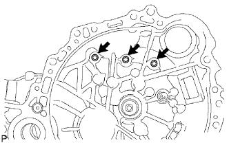 |
Remove the 3 bolts from the transaxle case side.
Remove the 14 bolts from the transaxle case side.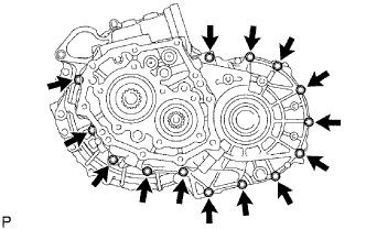
Remove the transaxle case by tapping it using a plastic-faced hammer.
| 31. REMOVE NO. 2 OIL RECEIVER PIPE |
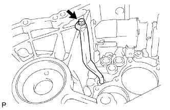 |
Remove the bolt and oil receiver pipe from the transaxle case.
- NOTICE:
- Do not damage the pipe.
| 32. REMOVE NO. 1 OIL RECEIVER PIPE |
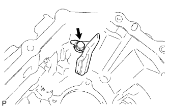 |
Remove the bolt and oil receiver pipe from the transaxle case.
- NOTICE:
- Do not damage the pipe.
| 33. REMOVE REVERSE RESTRICT PIN ASSEMBLY |
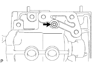 |
Using a 6 mm hexagon wrench, remove the restrict pin plug from the transaxle case.
Using a 5 mm pin punch and hammer, tap out the slotted pin.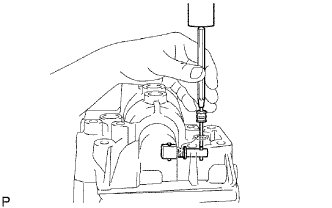
Remove the bolt, transmission oil baffle and reverse restrict pin.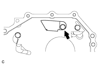
| 34. REMOVE TRANSAXLE MAGNET |
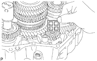 |
Remove the magnet from the transaxle case.
| 35. REMOVE REVERSE IDLER GEAR SUB-ASSEMBLY |
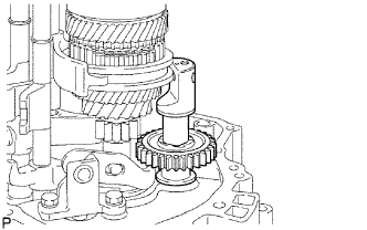 |
Remove the reverse idler gear with the reverse idler gear shaft from the transaxle case.
Remove the reverse idler gear and reverse idler thrust washer from the gear shaft.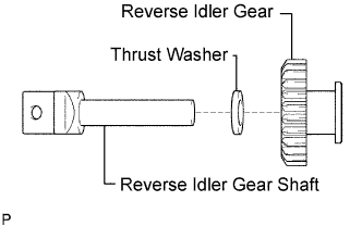
| 36. REMOVE REVERSE SHIFT ARM BRACKET ASSEMBLY |
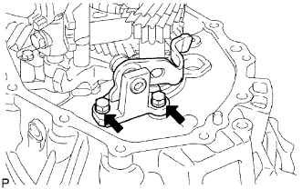 |
Remove the 2 bolts and arm bracket from the transaxle case.
| 37. REMOVE NO. 1 GEAR SHIFT FORK SHAFT |
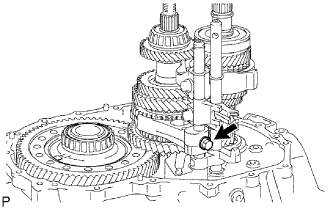 |
Remove the shift fork set bolt from the No. 1 gear shift fork.
Pull out the No. 1 gear shift fork shaft while the No. 3 gear shift fork shift is pulled up.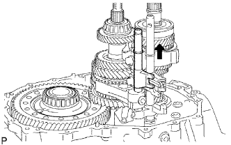
Using 2 screwdrivers and a hammer, tap out the shift fork shaft snap ring from the No. 1 gear shift fork shaft.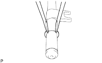
- HINT:
- Cover with a shop rag to keep the snap ring from flying off.
| 38. REMOVE REVERSE SHIFT FORK ROLLER |
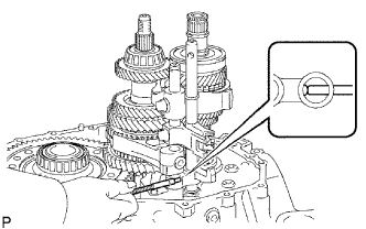 |
Using a magnetic finger, remove the reverse shift fork roller from the reverse shift fork.
| 39. REMOVE NO. 2 GEAR SHIFT FORK SHAFT |
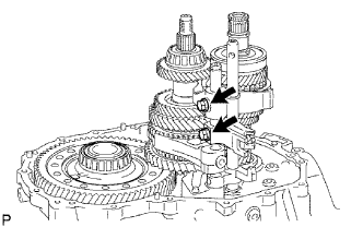 |
Remove the shift fork set bolt and shift head set bolt from the No. 2 gear shift fork and No. 1 gear shift head.
Remove the No. 2 gear shift fork shaft head and No. 1 gear shift head from the transaxle case.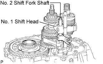
| 40. REMOVE NO. 1 GEAR SHIFT FORK |
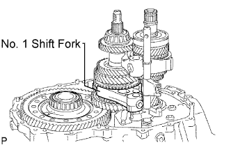 |
| 41. REMOVE NO. 3 GEAR SHIFT FORK SHAFT |
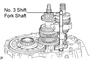 |
Remove the No. 3 gear shift fork shaft from the transaxle case.
Using 2 screwdrivers and a hammer, tap out the 2 shift fork shaft snap rings from the No. 3 gear shift fork shaft.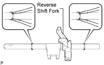
- HINT:
- Cover with a shop rag to keep the snap ring from flying off.
Remove the reverse shift fork from the No. 3 gear shift fork shaft.
| 42. REMOVE NO. 2 GEAR SHIFT FORK |
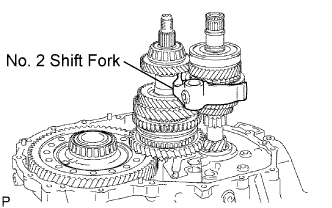 |
Remove the No. 2 gear shift fork from the input shaft.
| 43. REMOVE INPUT SHAFT ASSEMBLY |
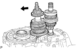 |
Tilt the output shaft, then remove the input shaft from the transaxle case.
| 44. REMOVE OUTPUT SHAFT ASSEMBLY |
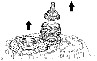 |
Slightly lift up on the differential case with the output shaft at an angle.
Remove the output shaft from the transaxle case.
| 45. REMOVE DIFFERENTIAL CASE ASSEMBLY |
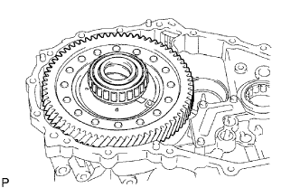 |
Remove the differential case from the transaxle case.
| 46. REMOVE MANUAL TRANSAXLE CASE RECEIVER |
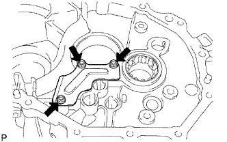 |
Remove the 3 bolts and receiver from the transaxle case.
| 47. REMOVE INPUT SHAFT FRONT BEARING |
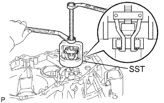 |
Using SST, remove the input shaft front bearing (outer race) from the transaxle case.
- SST
- 09612-65014
(09612-01040, 09612-01050)
| 48. REMOVE FRONT TRANSAXLE CASE OIL SEAL |
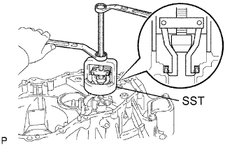 |
Using SST, remove the oil seal from the transaxle case.
- SST
- 09612-65014
(09612-01040, 09612-01050)
| 49. REMOVE FRONT OUTPUT SHAFT BEARING |
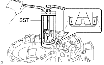 |
Using SST, remove the front bearing (outer race) from the transaxle case.
- SST
- 09387-00041
(09387-02020, 09387-02010)
| 50. REMOVE OUTPUT SHAFT COVER |
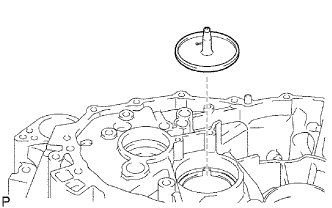 |
Remove the output shaft cover from the transaxle case.
| 51. REMOVE REAR OUTPUT SHAFT BEARING |
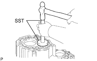 |
Using SST, tap out the rear bearing from the transaxle case (outer race).
- SST
- 09950-60010
(09951-00680)
09950-70010 (09951-07100)
| 52. REMOVE TRANSAXLE CASE OIL SEAL |
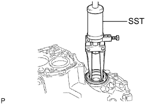 |
Using SST, tap out the oil seal from the transaxle case.
- SST
- 09308-00010
| 53. REMOVE FRONT TRANSAXLE CASE COVER OIL SEAL |
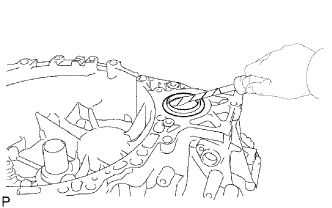 |
Using a screwdriver, pry out the cover oil seal.
- HINT:
- Tape the screwdriver tip before use to avoid damage.
| 54. REMOVE FRONT DIFFERENTIAL CASE FRONT TAPERED ROLLER BEARING |
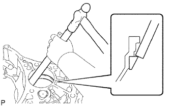 |
Using a brass bar and hammer, tap out the front tapered roller bearing (outer race) from the transaxle case.
Using SST, remove the case front tapered roller bearing from the front differential case.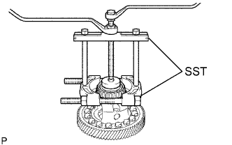
- SST
- 09950-00020
09950-00030
09950-40011 (09957-04010)
09950-60010 (09951-00560)
| 55. REMOVE FRONT DIFFERENTIAL CASE REAR TAPERED ROLLER BEARING |
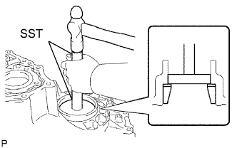 |
Using SST and a hammer, tap out the rear tapered roller bearing (outer race) and rear shim from the transaxle case.
- SST
- 09950-60020
(09951-00790)
09950-70010 (09951-07100)
Using SST, remove the rear tapered roller bearing (inner race) from the front differential case.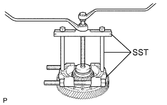
- SST
- 09950-00020
09950-00030
09950-40011 (09957-04010)
09950-60010 (09951-00490)
| 56. REMOVE NO. 3 TRANSAXLE HUB SLEEVE |
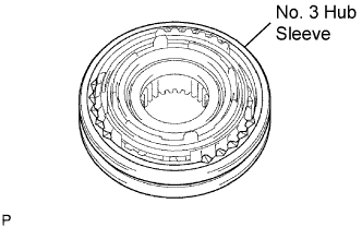 |
Remove the No. 3 transaxle hub sleeve from the No. 3 transaxle clutch hub.
| 57. REMOVE NO. 3 SYNCHROMESH SHIFTING KEY SPRING |
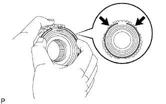 |
Remove the 2 No. 3 synchromesh shifting key springs and synchronizer ring set from the No. 3 transaxle clutch hub while pushing on the No. 3 synchromesh shifting key spring.
| 58. REMOVE SYNCHRONIZER PULL RING |
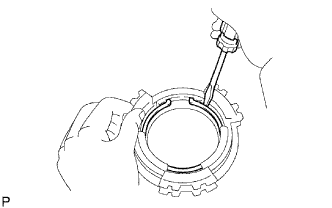 |
Using a screwdriver, remove the synchronizer pull ring snap ring.
Remove the synchronizer pull ring, No. 5 synchronizer ring outer, No. 5 synchronizer ring inner and No. 5 synchronizer ring middle.