INSTALLATION
Removal / installation · Vehicles built from Aug 2007
Versions by build date: Nov 2005 – Dec 2006 Jan 2007 – Jul 2007 from Aug 2007
| 1.
INSTALL REAR NO. 1 SEAT ASSEMBLY RH |
 |
Fully tilt the seatback forward.
Place the seat in the cabin.
- NOTICE:
- Be careful not to damage the vehicle body.
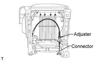
Connection procedures of seat to lock cable when reusing seat:
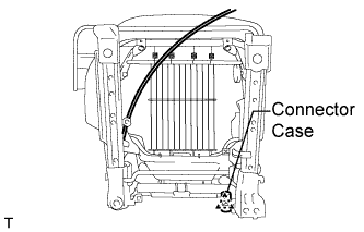
- Using a screwdriver, detach the claw and remove the connector case from the seat.
- HINT:
- Tape the screwdriver tip before use.
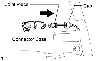
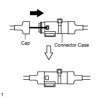
- Install the connector case to the body's cap.
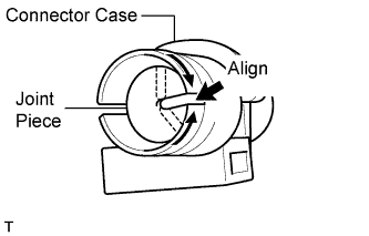
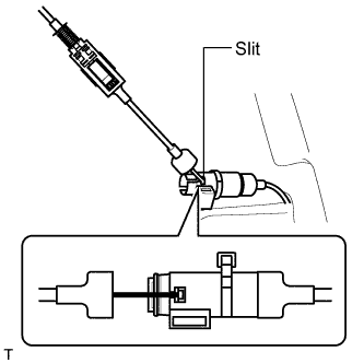
- Pull out the joint piece. Align the slits of the joint piece and connector case.
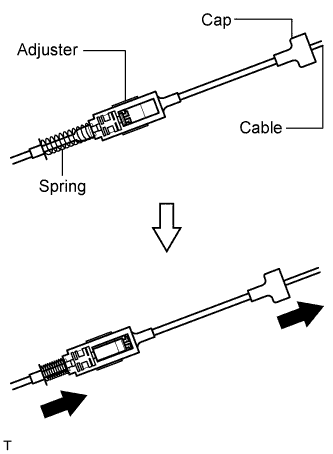
- Compress the spring of the adjuster, and pull out the cable from the seat's cap.
- HINT:
- Perform this procedure with the lock of the adjuster released.
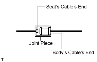
- Install the seat cable's end part to the connector case's slit.
- HINT:
- Position the joint piece cable's end part as shown in the illustration.
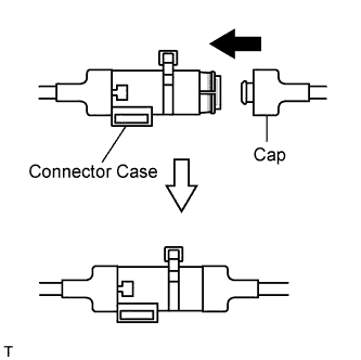
- Install the seat's cap to the connector case.
Temporarily place the seat into the vehicle where it will be installed.
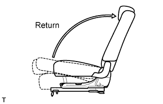
- Return the seatback to the upright position.
- Attach the claws of the connector and adjuster, and install them to the seat.
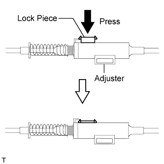
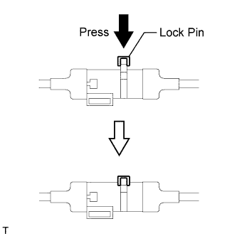
- Press the adjuster's lock piece to lock it.
- NOTICE:
- When pressing the lock piece, make sure the adjuster's spring is not compress.
Connection procedures of seat to lock cable when replacing seat:
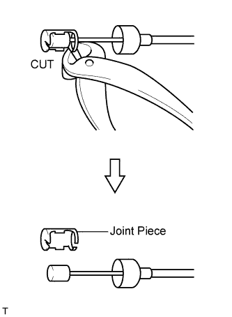
- Cut the joint piece on the lock cable, and remove it.
- HINT:
- A joint piece is included with new seats.
- This procedure is not necessary when the lock cable is replaced with a new one.
Temporarily place the seat into the vehicle where it will be installed.
- Install the body's cap to the connector case.
- Press the adjuster's lock pin.
- Return the seatback to the upright position.
- Press the adjuster's lock piece to lock it.
- NOTICE:
- When pressing the lock piece, make sure the adjuster's spring is not compressed.
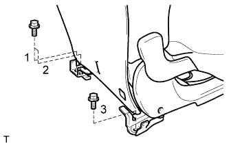
Lift up the seat track adjusting handle and move the seat to the foremost position.
- Tighten the 2 bolts on the rear side of the seat.
-
Torque:
- 42 N*m{
428 kgf*cm
, 31 ft.*lbf
}
- HINT:
- Tighten the bolts in the order indicated in the illustration.
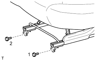
Lift up the seat track adjusting handle and move the seat to the rearmost position.
- Tighten the 2 bolts on the front side of the seat.
-
Torque:
- 42 N*m{
428 kgf*cm
, 31 ft.*lbf
}
- HINT:
- Tighten the bolts in the order indicated in the illustration.
| 2.
INSTALL REAR NO. 1 SEAT LOCK CABLE ASSEMBLY |
|
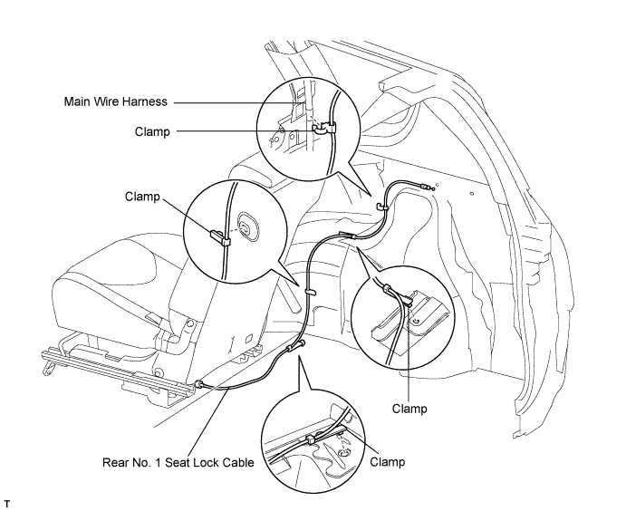
Attach the clamps and install the cable to the vehicle body.

| 3.
INSTALL REAR SEAT LEG COVER |
|
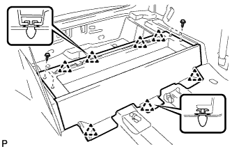
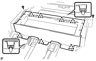
- Attach the 8 claws to install the 2 leg covers.
| 4.
INSTALL REAR NO. 3 SEAT LEG SIDE COVER |
|
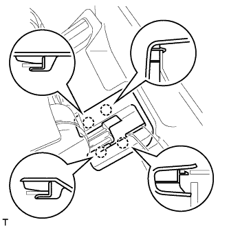
- Attach the 4 claws to install the No. 3 rear seat leg side cover.
| 5.
INSTALL REAR NO. 2 SEAT LEG SIDE COVER |
|
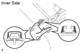
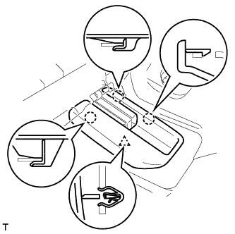
- Attach the 3 claws and clip to install the rear No. 2 seat leg side cover.
| 6.
INSTALL RECLINING REMOTE CONTROL LEVER SUB-ASSEMBLY RH |
|
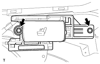
Connect the rear No. 1 seat lock cable to the lever.
- Install the lever with the 2 bolts.
-
Torque:
- 18 N*m{
184 kgf*cm
, 13 ft.*lbf
}
| 7.
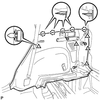
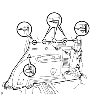
INSTALL DECK TRIM SIDE PANEL ASSEMBLY RH (for Short Body)
|
|
Install the belt hanger to the trim board.
Attach the 5 clips and 5 claws to install the trim board.
Install the bolt and 2 screws.
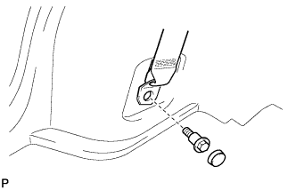
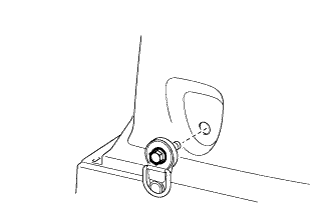
- Connect the rear No.1 seat belt's floor anchor.
Connect the floor anchor with the bolt.
-
Torque:
- 42 N*m{
428 kgf*cm
, 31 ft.*lbf
}
Install the anchor cover.
| 8.
INSTALL DECK TRIM SIDE PANEL ASSEMBLY RH (for Long Body)
|
|
- Install the belt hanger to the trim board.
Attach the 4 clips and 5 claws to install the trim board.
Install the 2 screws and 2 bolts.
- Connect the rear No.1 seat belt's floor anchor.
Connect the floor anchor with the bolt.
-
Torque:
- 42 N*m{
428 kgf*cm
, 31 ft.*lbf
}
Install the anchor cover.
| 9.
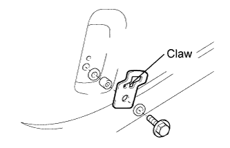
INSTALL CHILD RESTRAINT SEAT TETHER ANCHOR BRACKET (for Short Body)
|
|
Align the bracket positioning hole with the claws and install the bracket with the bolt, 2 washers and collar.
-
Torque:
- 42 N*m{
428 kgf*cm
, 31 ft.*lbf
}
| 10.
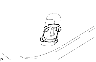
INSTALL CHILD RESTRAINT SEAT TETHER ANCHOR COVER (for Short Body)
|
|
Attach the 4 claws to install the cover.
| 11.
INSTALL TETHER ANCHOR BRACKET SUB-ASSEMBLY (for Long Body)
|
|
- Install the tether anchor bracket with the bolt.
-
Torque:
- 42 N*m{
428 kgf*cm
, 31 ft.*lbf
}
| 12.
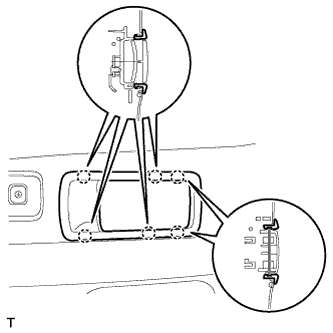
INSTALL RECLINING REMOTE CONTROL LEVER BEZEL RH |
|
- Attach the 6 claws to install the bezel.
| 13.
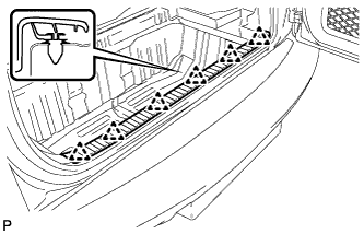
INSTALL REAR FLOOR FINISH PLATE (for Short Body)
|
|
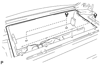
- Attach the 6 clips to install the finish plate.
| 14.
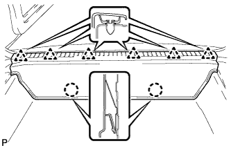
INSTALL REAR FLOOR FINISH PLATE (for Long Body)
|
|
- Attach the 2 claws and 6 clips to install the finish plate.
| 15.
INSTALL BACK DOOR WEATHERSTRIP |
|
| 16.
INSTALL REAR FLOOR NO. 1 MAT SUPPORT SIDE PLATE (for Short Body)
|
|
Attach the 7 clips to install the side plate.
Install the 4 screws.
| 17.
INSTALL REAR FLOOR NO. 1 MAT SUPPORT SIDE PLATE (for Long Body)
|
|
Attach the 7 clips to install the side plate.
Install the 4 screws.
| 18.
INSTALL JACK CARRIER ASSEMBLY (for Short Body)
|
|
- Install the jack carrier with the 7 clips.
| 19.
INSTALL REAR FLOOR NO. 3 BOARD |
|
| 20.
INSTALL REAR FLOOR NO. 2 BOARD |
|
| 21.
INSTALL DECK BOARD ASSEMBLY |
|
| 22.
INSTALL REAR FLOOR NO. 1 BOARD |
|
| 23.
INSTALL TONNEAU COVER ASSEMBLY |
|
| 24.
INSTALL PACKAGE TRAY TRIM POCKET SUB-ASSEMBLY |
|