C1241/41 Low Battery Positive Voltage
Diagnostic trouble codes · Vehicles built Aug 2007 – Jul 2008
Versions by build date: Nov 2005 – Dec 2006 Jan 2007 – Jul 2007 Aug 2007 – Jul 2008
DESCRIPTION
When there is an abnormality in the power supply circuit of the brake actuator (skid control ECU), the skid control ECU sets a DTC and the operation is prohibited by the fail-safe function. This DTC is set when the voltage supplied to terminal IG1 is outside the DTC detection threshold, due to abnormalities of the battery, power source circuits or charging circuits such as the alternator circuit.The fail-safe function is canceled when the voltage to terminal IG1 returns to normal.
| DTC No. |
DTC Detection Condition |
Trouble Area |
| C1241/41 |
When one of following conditions is met:
|
|
WIRING DIAGRAM
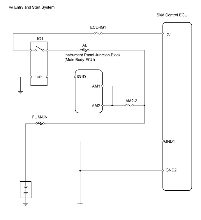

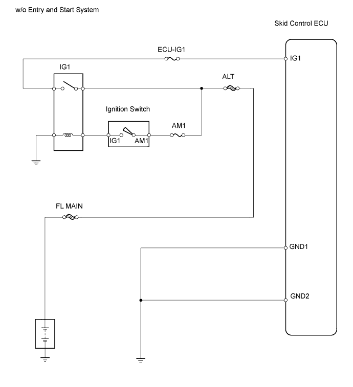
INSPECTION PROCEDURE
| 1. INSPECT FUSE (ECU-IG1) |

Remove the ECU-IG1 fuse from the instrument panel junction block.
Measure the resistance of the fuse.
- Standard resistance:
- Below 1 Ω
|
|
||||

| OK | |
 |
| 2. INSPECT BATTERY |
Check the battery voltage.
- Standard voltage:
- 11 to 14 V
|
|
||||
| OK | |
|
| 3. CHECK WIRE HARNESS (SKID CONTROL ECU - BATTERY) |
Disconnect the A26 ECU connector.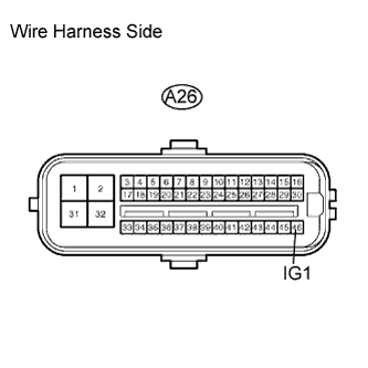
Measure the voltage of the wire harness side connector.
- Standard voltage:
Tester Connection
Condition
Specified Condition
A26-46 (IG1) - Body ground
Ignition switch on (IG)
10 to 14 V
|
|
||||
| OK | |
|
| 4. CHECK WIRE HARNESS (SKID CONTROL ECU - BODY GROUND) |
Disconnect the A26 ECU connector.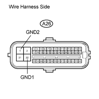
Measure the resistance of the wire harness side connector.
- Standard resistance:
Tester Connection
Specified Condition
A26-32 (GND1) - Body ground
Below 1 Ω
A26-1 (GND2) - Body ground
Below 1 Ω
|
|
||||
| OK | |
|
| 5. RECONFIRM DTC |
Clear the DTC (Click here).
Drive the vehicle at 3 km/h (2 mph) or more for several seconds.
Check if the same DTC is output (Click here).
Result Result
Proceed to
DTC is output
A
DTC is not output
B
|
|
||||
| A | ||
 |
||
| ||