NAVIGATION SYSTEM (for DVD) > SYSTEM DESCRIPTION |
| NAVIGATION SYSTEM OUTLINE |
Vehicle position tracking methods
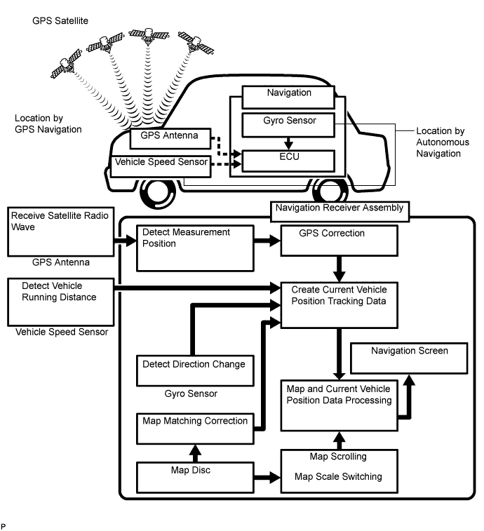
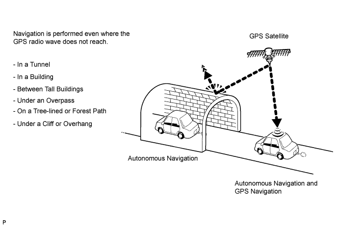
It is essential that the navigation system correctly tracks the current vehicle position and displays it on the map. There are 2 methods to track the current vehicle position: autonomous (dead reckoning) and GPS* (satellite) navigation. Both navigation methods are used in conjunction with each other.

| Operation | Description |
| Vehicle Position Calculation | The navigation receiver assembly calculates the current vehicle position (direction and current position) using the direction deviation signal from the gyro sensor and running distance signal from the vehicle speed sensor and creates the driving route. |
| Map Display Processing | The navigation receiver assembly processes the vehicle position data, vehicle running track, and map data from the map disc. |
| Map Matching | The map data from the map disc is compared to the vehicle position and running track data. Then, the vehicle position is matched with the nearest road. |
| GPS Correction | The vehicle position is matched to the position measured by the GPS. Then, the measurement position data from the GPS unit is compared with the vehicle position and running track data. If the position is very different, the GPS measurement position is used. |
| Distance Correction | The running distance signal from the vehicle speed sensor includes error caused by tire wear and slippage between the tires and road surface. Distance correction is performed to account for this. The navigation ECU automatically offsets the running distance signal to make up for the difference between it and the distance data of the map. The offset is automatically updated. |

Autonomous navigation
This method determines the relative vehicle position based on the running track determined by the gyro and vehicle speed sensors.
Gyro sensor
Calculates the direction by detecting angular velocity. It is located in the navigation receiver assembly.
Vehicle speed sensor
Used to calculate the vehicle running distance.
GPS navigation (satellite navigation)
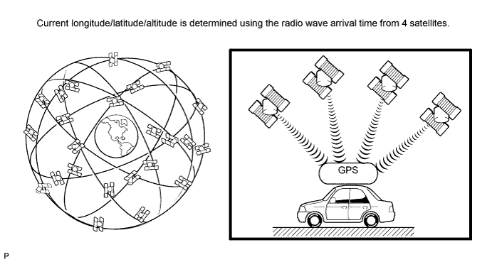
This method detects the absolute vehicle position using radio waves from a GPS satellite*.

| Number of Satellites | Measurement | Description |
| 2 or less | Measurement is impossible | The vehicle position cannot be obtained because the number of satellites is not enough. |
| 3 | 2-dimensional measurement is possible | The vehicle position is obtained based on current longitude and latitude (this is less precise than 3-dimensional measurement). |
| 4 | 3-dimensional measurement is possible | The vehicle position is obtained based on current longitude, latitude and altitude. |
Map matching
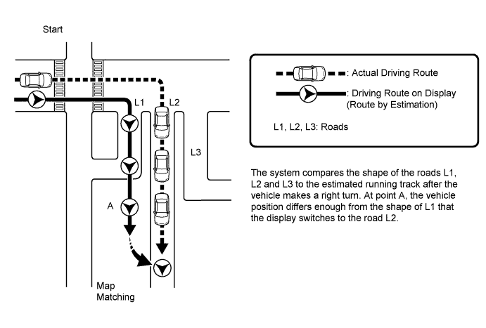
The current driving route is calculated by autonomous navigation (according to the gyro sensor and vehicle speed sensor) and GPS navigation. This information is then compared with possible road shapes from the map data in the map disc and the vehicle position is set onto the most appropriate road.
| NAVIGATION RECEIVER ASSEMBLY OUTLINE |
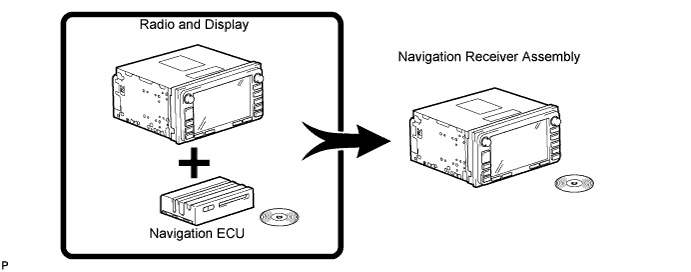
Conventionally, 2 separate devices, a "radio and display" and a "navigation ECU" are used. This model combines these devices into a signal unit.

| TOUCH SCREEN OUTLINE |
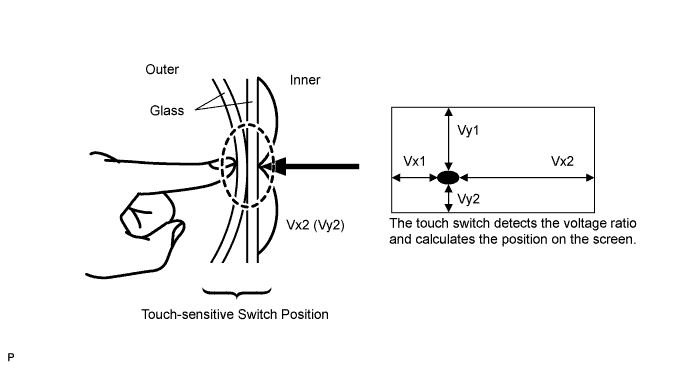
Touch switches are touch-sensitive (interactive) switches operated by touching the screen. When a switch is pressed, the outer glass bends to contact the inner glass at the pressed position. By doing this, the voltage ratio is measured and the pressed position is detected.

| DVD (Digital Versatile Disc) PLAYER OUTLINE (for Navigation Map) |
The navigation receiver assembly uses a laser pickup to read the digital signals recorded on a DVD.
| CD (Compact Disc) PLAYER OUTLINE |
A compact disc player uses a laser pickup to read digital signals recorded on a compact disc (CD). By converting the digital signals to analog, it can play music and other content.
Usable discs
This player can play only audio CDs, CD-Rs (CD-Recordable) and CD-RWs (CD-ReWritable) that have any of the following marks:

Precautions for use of discs
![]() |
Cleaning
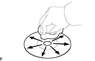
If dirt is on the disc surface, wipe it clean with a soft dry cloth, such as an eyeglass cleaner for plastic lenses, from the inside to the outside in a radial direction.
| MP3/WMA OUTLINE |
Playable MP3 file standards
| Compatible Standard | MP3 (MPEG1 LAYER3, MPEG2 LSF LAYER3) |
| Compatible sampling frequency |
|
| Compatible bit rate |
|
| Compatible channel mode | Stereo, joint stereo, dual channel, monaural |
Playable WMA file standards
| Compatible Standard | WMA Ver. 7, 8, and 9 |
| Compatible sampling frequency | 44.1, 48 (kHz) |
| Compatible bit rate |
|
ID3 tag and WMA tag
Additional textual information called an ID3 tag can be input to MP3 files. Information such as song titles and artist names can be stored.
Additional textual information called a WMA tag can be input to WMA files. Information such as song titles and artist names can be stored.
Usable media
Only CD-ROMs, CD-Rs (CD-Recordable) and CD-RWs (CD-ReWritable) can be used to play MP3/WMA files.
Usable media format
Usable media format
| Disc format | CD-ROM Mode 1, CD-ROM XA Mode 2 Form 1 |
| File format | ISO 9660 Level 1 and Level 2 (Joliet, Romeo) |
Standards and restrictions
| Maximum directory levels | 8 levels |
| Maximum number of characters for a folder name/file name | 32 characters |
| Maximum number of folders | 192 (Including empty folders, route folders and folders that do not contain MP3/WMA files) |
| Maximum number of files in a disc | 255 (Including non-MP3/WMA files) |
File names
Only files with an extension of ".mp3" or ".wma" can be recognized and played as MP3 or WMA files.
Save MP3 or WMA files with an extension of ".mp3" or ".wma".
| "BLUETOOTH" OUTLINE |
"Bluetooth" is a trademark owned by Bluetooth SIG, Inc.
"Bluetooth" is a new wireless connection technology that uses the 2.4 GHz frequency band.
Handsfree function
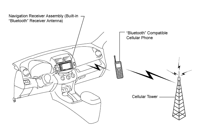
The "Bluetooth" built into the navigation receiver assembly and a "Bluetooth" compatible cellular phone* can be connected using a "Bluetooth" wireless connection. This enables use of the handsfree function on the cellular phone even though the phone may be in a pocket or bag. For this reason, it is not necessary to use a connector or cable to connect the cellular phone.

"Bluetooth" audio function
The "Bluetooth" built into the navigation receiver assembly and a "Bluetooth" compatible portable audio player* can be connected using a "Bluetooth" wireless connection. This enables files stored in the portable audio player to be heard from the vehicle speakers. In addition, operations such as play/stop can be performed directly from the navigation receiver assembly.
*: Some versions of "Bluetooth" compatible audio players may not be able to operate the "Bluetooth" function, or music may play, but functions available using the navigation receiver assembly may be limited.
Available "Bluetooth" audio devices
| "Bluetooth" specifications | Ver. 1.1, or higher (Recommended: Ver. 2.0 + EDR or higher) |
| Following Profiles |
|
| Maximum number of audio devices that can be registered | 2 |
| RADIO DESCRIPTION |
Radio frequency band
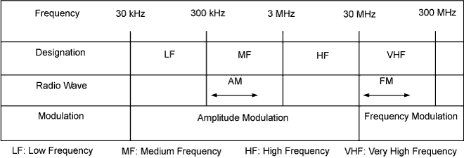
Radio broadcasts use the radio frequency bands shown in the table below.

![]() |
Service area
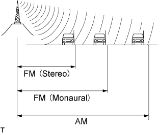
The service areas of AM and FM broadcasts are vastly different. Sometimes an AM broadcast can be received very clearly but an FM stereo broadcast cannot. FM stereo has the smallest service area, and is prone to pick up static and other types of interference such as noise.
Radio reception problems
![]() |
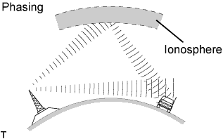
Phasing
AM broadcasts are susceptible to electrical interference and another kind of interference called phasing. Occurring only at night, phasing is the interference created when a vehicle receives 2 radio wave signals from the same transmitter. One signal is reflected off the ionosphere and the other signal is received directly from the transmitter.
![]() |
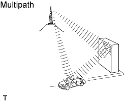
Multipath
Multipath is a type of interference created when a vehicle receives 2 radio wave signals from the same transmitter. One signal is reflected off buildings or mountains and the other signal is received directly from the transmitter.
![]() |
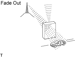
Fade out
Fade out is caused by objects (buildings, mountains, and other such large obstacles) that deflect away part of a signal, resulting in a weaker signal when the object is between the transmitter and vehicle. High frequency radio waves, such as FM broadcasts, are easily deflected by obstructions. Low frequency radio waves, such as AM broadcasts, are much more difficult to deflect.
Noise problem
Technicians must have a clear understanding about each customer noise complaint. Use the following table to diagnose noise problems.
| Radio Frequency | Noise Occurrence Condition | Presumable Cause |
| AM | Noise occurs in a specified area | Foreign noise |
| AM | Noise occurs when listening to an intermittent broadcast | An identical program transmitted from multiple towers can cause noise where the signals overlap |
| AM | Noise occurs only at night | Music beat from a distant broadcast |
| FM | Noise occurs while driving in a specified area | Multipath or phasing noise resulting from a change in FM frequency |
| AUTOMATIC SOUND LEVELIZER (ASL) FUNCTION OUTLINE |
The ASL function automatically adjusts the sound volume in order to enable clear audio quality even when vehicle noise increases (as vehicle speed increases, the volume is turned up, etc.).
Vehicle speed signals are received from the combination meter assembly and used by ASL control.
| DIAGNOSTIC FUNCTION OUTLINE |
The navigation system has a diagnostic function (the result is indicated on the master unit).
Each component has a specified number (3 digits) called a physical address. Each function has a number (2 digits) called a logical address.
A 3-digit hexadecimal component code (physical address) is allocated to each component on the AVC-LAN. Using this code, the component can be indicated in the diagnostic function.
| DIAGNOSIS DISPLAY DETAILED DESCRIPTION |
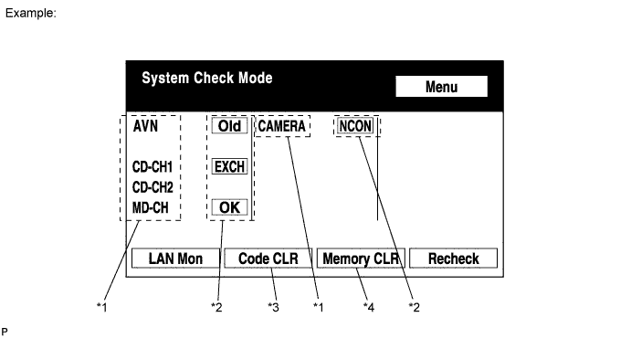
SYSTEM CHECK
System Check Mode Screen

| Address No. | Name | Address No. | Name |
| 110 | EMV | 120 | AVX |
| 128 | 1DIN TV | 140 | AVN |
| 144 | G-BOOK | 178 | NAVI |
| 17C | MONET | 190 | AUDIO H/U |
| 1AC | CAMERA-C | 1B0 | Rr-TV |
| 1C0 | Rr-CONT | 19D | BT-HF |
| 1C4 | PANEL | 1C6 | G/W |
| 1C8 | FM-M-LCD | 1D8 | CONT-SW |
| 1EC | Body | 118 | EMVN |
| 1F1 | XM | 1F2 | SIRIUS |
| 230 | TV-TUNER | 240 | CD-CH2 |
| 250 | DVD-CH | 280 | CAMERA |
| 360 | CD-CH1 | 3A0 | MD-CH |
| 17D | TEL | 440 | DSP-AMP |
| 530 | ETC | 1F6 | RSE |
| 1A0 | DVD-P | 1D6 | CLOCK |
| 238 | DTV | 480 | AMP |
| 1F8 | DAB-TUNER | - | - |
| Result | Meaning | Action |
| OK | Device did not respond with DTC (excluding communication DTCs from AVC-LAN). | - |
| EXCH | Device responds with "replace" type DTC. | Look up DTC in "Unit Check Mode" and replace device. |
| CHEK | Device responds with "check" type DTC. | Look up DTC in "Unit Check Mode". |
| NCON | Device was previously present, but does not respond in diagnostic mode. |
|
| Old | Device responds with "old" type DTC. | Look up DTC in "Unit Check Mode". |
| NRES | Device responds in diagnostic mode, but gives no DTC information. |
|
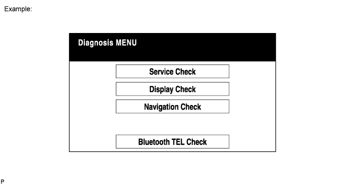
Diagnosis MENU Screen

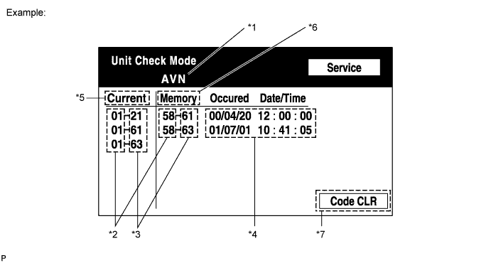
Unit Check Mode Screen

| Display | Content |
| *1: Device name | Target device |
| *2: Segment | Logical address of target device |
| *3: DTC | DTC (Diagnostic Trouble Code) |
| *4: Timestamp | Time and date of past DTCs are displayed (year is displayed in 2-digit format) |
| *5: Present Code | DTCs output at service check are output |
| *6: Past Code | Diagnostic memory results and stored DTCs are output |
| *7: Diagnosis Clear Switch | Pushing this switch for 3 seconds clears diagnostic memory data of target device (responses to diagnostic system check result and displayed data are cleared) |
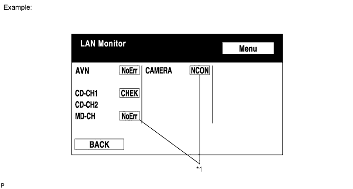
LAN Monitor (Original) Screen

| Result | Meaning | Action |
| No Err (OK) | There are no communication DTCs. | - |
| CHEK | Device responds with "check" type DTC. | Look up DTC in "Unit Check Mode". |
| NCON | Device was previously present, but does not respond in diagnostic mode. |
|
| Old | Device responds with "old" type DTC. | Look up DTC in "Unit Check Mode". |
| NRES | Device responds in diagnostic mode, but gives no DTC information. |
|
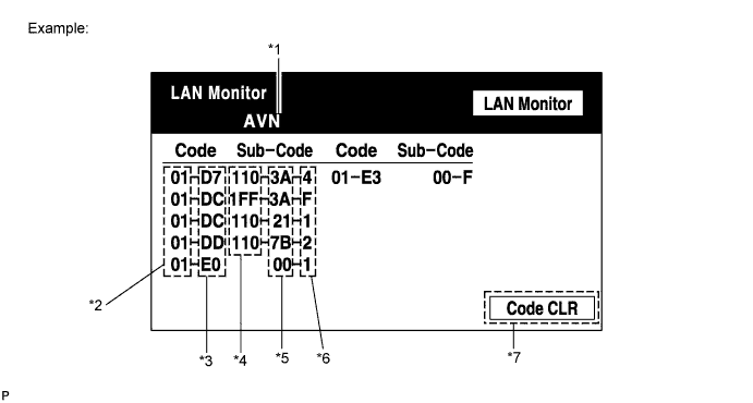
LAN Monitor (Individual) Screen

| Display | Content |
| *1: Device name | Target device |
| *2: Segment | Logical address of target device |
| *3: DTC | DTC (Diagnostic Trouble Code) |
| *4: Sub-code (device address) | Physical address stored with DTC (if there is no address, nothing is displayed) |
| *5: Connection check No. | Connection check number stored with DTC |
| *6: DTC occurrence | Number of times same DTC has been stored |
| *7: Diagnosis Clear Switch | Pushing this switch for 3 seconds clears diagnostic memory data of target device (responses to diagnostic system check result and displayed data are cleared) |
DISPLAY CHECK
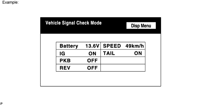
Vehicle Signal Check Mode Screen

| Name | Content |
| Battery | Battery voltage is displayed. |
| PKB | Parking brake ON/OFF state is displayed. |
| REV | Reverse signal ON/OFF state is displayed. |
| IG | Ignition switch ON/OFF state is displayed. |
| TAIL | TAIL signal (light control switch) ON/OFF state is displayed. |
| SPEED | Vehicle speed is displayed in km/h. |
NAVIGATION CHECK
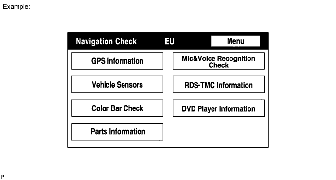
Navigation Check Screen

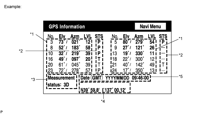
GPS Information Screen

| Display | Content |
| T | System is receiving GPS signal, but is not using it for location. |
| P | System is using GPS signal for location. |
| - | System cannot receive GPS signal. |
| Display | Content |
| 01H | System cannot receive a GPS signal. |
| 02H | System is tracing a satellite. |
| 03H | System is receiving a GPS signal, but is not using it for location. |
| 04H | System is using the GPS signal for location. |
| Display | Content |
| 2D | 2-dimensional location method is being used. |
| 3D | 3-dimensional location method is being used. |
| NG | Location data cannot be used. |
| Error | Reception error has occurred. |
| - | Any other state. |
| Display | Content |
| Position | Latitude and longitude information on current position is displayed. |
| Display | Content |
| Date | Date/time information obtained from GPS signal is displayed in Greenwich Mean Time (GMT). |
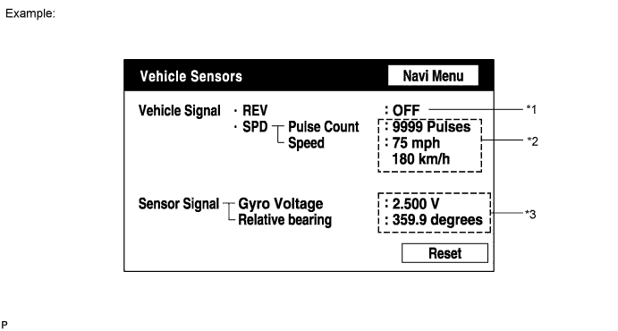
Vehicle Sensors Screen

| Display | Content |
| *1: REV | REV signal ON/OFF state is displayed. |
| *2: SPD | SPD signal condition is displayed. |
| Display | Content |
| *3: Gyro sensor | Gyro sensor output condition is displayed (when vehicle is driven straight or is stationary, voltage is approximately 2.5 V). |
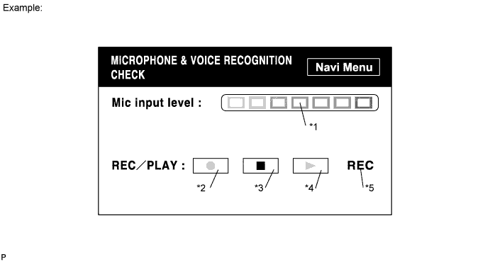
Microphone & Voice Recognition Check Screen

| Display | Contents |
| *1: Microphone input level meter | Monitors the microphone input level every 100 msec. and displays results in 8 different levels. |
| *2: Recording switch | Starts recording. |
| *3: Stop switch | Stops recording. |
| *4: Play switch | Plays recorded voice. |
| *5: Recording indicator | Comes on while recording. |
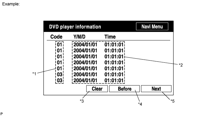
DVD Player Information Screen

| Display | Contents |
| *1: Trouble code | Each code corresponding to malfunctions is displayed. For details, refer to "Trouble Code Description". |
| *2: Occurrence time |
|
| *3: Trouble code clear switch | All code data being displayed is cleared by pushing this switch for 3 seconds. |
| *4: Return switch | Previous page is displayed. If current displayed page is first page, this switch cannot be operated. |
| *5: Proceed switch | Next page is displayed. If current displayed page is last page, this switch cannot be operated. |
| Code | Malfunction | Countermeasure |
| 01 | Cannot be recognized | Replace navigation receiver assembly. |
| 03 | Cannot be read | Follow inspection procedure for DTC 58-42 (Click here). |