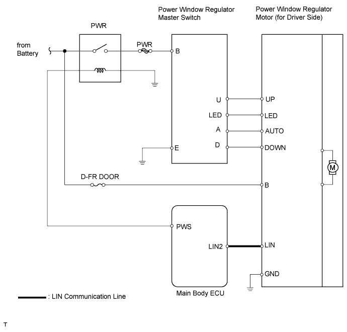
POWER WINDOW CONTROL SYSTEM > Driver Side Power Window does not Operate with Power Window Master Switch |
| 1.CHECK DTC |
Check for DTCs.
Connect the intelligent tester to the DLC3.
By following the tester screen display, check whether any DTCs are output.
| Display | Proceed to |
| No output | A |
| DTC output | B |
|
| ||||
| A | |
 |
| 2.PERFORM ACTIVE TEST USING INTELLIGENT TESTER (POWER WINDOW UP/DOWN) |
Perform the Active Test, using the intelligent tester to generate a control command, and then check the power window operation.
| Item | Test Details | Diagnostic Note |
| Power Window | OFF / UP / DOWN (OFF) | - |
|
| ||||
| OK | |
|
| 3.READ VALUE USING INTELLIGENT TESTER (MASTER SWITCH) |
Check the Data List for proper functioning of the power window master switch.
| Item | Measurement Item / Display (Range) | Normal Condition | Diagnostic Note |
| D P/W Auto Switch | Driver side power window AUTO switch signal / ON or OFF | ON: Driver side power window AUTO switch operates OFF: Driver side power window AUTO switch does not operate | - |
| D P/W Up Switch | Driver side power window UP switch signal / ON or OFF | ON: Driver side power window UP switch operates OFF: Driver side power window UP switch does not operate | - |
| D P/W Down Switch | Driver side power window DOWN switch signal / ON or OFF | ON: Driver side power window DOWN switch operates OFF: Driver side power window DOWN switch does not operate | - |
|
| ||||
| NG | |
|
| 4.CHECK WIRE HARNESS (SWITCH INPUT POWER SUPPLY) |
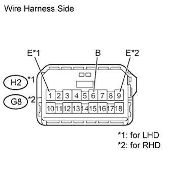 |
Disconnect the H2*1 or G8*2 switch connector.
Turn the ignition switch on (IG).
Measure the voltage of the wire harness side connector.
| Tester Connection | Specified Condition |
| H2-6 (B) - H2-1 (E) | 10 to 14 V |
| Tester Connection | Specified Condition |
| G8-6 (B) - G8-9 (E) | 10 to 14 V |
|
| ||||
| OK | |
|
| 5.CHECK WIRE HARNESS (MASTER SWITCH - REGULATOR MOTOR) |
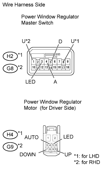 |
Disconnect the H2*1 or G8*2 switch connector.
Disconnect the H4*1 or G9*2 motor connector.
Measure the resistance of the wire harness side connectors.
| Tester Connection | Specified Condition |
| H2-8 (U) - H4-10 (UP) | Below 1 Ω |
| H2-5 (D) - H4-7 (DOWN) | Below 1 Ω |
| H2-4 (A) - H4-4 (AUTO) | Below 1 Ω |
| H2-3 (LED) - H4-5 (LED) | Below 1 Ω |
| Tester Connection | Specified Condition |
| G8-1 (U) - G9-10 (UP) | Below 1 Ω |
| G8-5 (D) - G9-7 (DOWN) | Below 1 Ω |
| G8-4 (A) - G9-4 (AUTO) | Below 1 Ω |
| G8-3 (LED) - G9-5 (LED) | Below 1 Ω |
|
| ||||
| OK | ||
 | ||
| ||
| 6.INSPECT FUSE (D FR DOOR) |
Remove the D FR DOOR fuse from the instrument panel junction block.
|
| ||||
| OK | |
|
| 7.CHECK WIRE HARNESS (MOTOR INPUT POWER SUPPLY) |
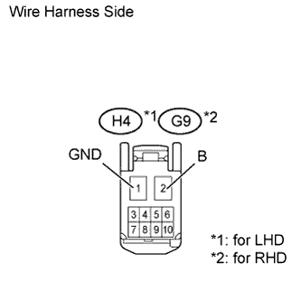 |
Disconnect the H4*1 or G9*2 motor connector.
Turn the ignition switch on (IG).
Measure the voltage of the wire harness side connector.
| Tester Connection | Specified Condition |
| H4-2 (B) - H4-1 (GND) | 10 to 14 V |
| Tester Connection | Specified Condition |
| G9-2 (B) - G9-1 (GND) | 10 to 14 V |
|
| ||||
| OK | ||
| ||
| ||

