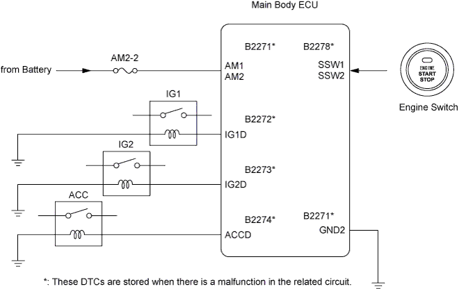
ENTRY AND START SYSTEM > Power Source Mode does not Change |
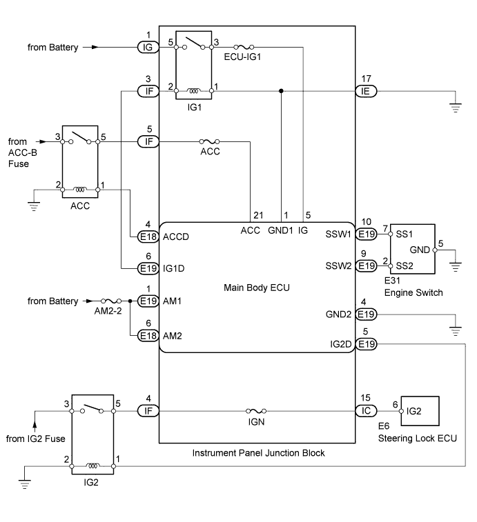
| 1.CHECK WHETHER DTC OUTPUT OCCURS |
Connect the intelligent tester to the DLC3.
Turn the engine switch on (IG) and turn the intelligent tester on.
Enter the following menus: Body / Main Body / DTC.
Clear the DTCs.
Check for DTCs again.
|
| ||||
| OK | |
 |
| 2.CHECK ENTRY AND START SYSTEM |
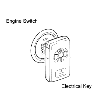 |
Remove the battery of the electrical key transmitter (Click here).
With the clutch pedal depressed, touch the TOYOTA mark of the key to the engine switch.
When operating the engine switch, check whether the engine switch changes to on (ACC) or on (IG).
| Result | Proceed to |
| Does not change to on (ACC) or on (IG) | A |
| Changes to on (ACC) and on (IG) | B |
|
| ||||
| A | |
|
| 3.INSPECT FUSE (AM2-2) |
Remove the AM2-2 fuse from the engine room No. 1 relay block.
Measure the resistance according to the value(s) in the table below.
| Tester Connection | Condition | Specified Condition |
| AM2-2 fuse | Always | Below 1 Ω |
|
| ||||
| OK | |
|
| 4.READ VALUE USING INTELLIGENT TESTER (RELAY MONITOR) |
Connect the intelligent tester to the DLC3.
Turn the engine switch on (IG) and turn the intelligent tester on.
Enter the following menus: Body / Main Body / Data List.
Read the display on the intelligent tester.
| Tester Display | Measurement Item/Range | Normal Condition | Diagnostic Note |
| IG1 Relay Monitor(Inside) | IG1 inner relay monitor/ON or OFF | ON: Engine switch on (IG) OFF: Engine switch off | - |
| IG2 Relay Monitor(Inside) | IG2 inner relay monitor/ON or OFF | ON: Engine switch on (IG) OFF: Engine switch off | - |
| ACC Relay Monitor | ACC relay monitor/ON or OFF | ON: Engine switch on (ACC) OFF: Engine switch off | - |
|
| ||||
| OK | ||
 | ||
| ||
| 5.INSPECT IG1 RELAY |
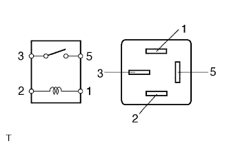 |
Inspect the IG1 relay.
Remove the IG1 relay from the instrument panel junction block.
Measure the resistance according to the value(s) in the table below.
| Tester Connection | Condition | Specified Condition |
| 3 - 5 | Battery voltage is applied to terminals 1 and 2 | Below 1 Ω |
| 3 - 5 | Battery voltage is not applied to terminals 1 and 2 | 10 kΩ or higher |
|
| ||||
| OK | |
|
| 6.INSPECT IG2 RELAY |
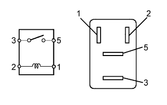 |
Inspect the IG2 relay.
Remove the IG2 relay from the engine room No. 1 relay block.
Measure the resistance according to the value(s) in the table below.
| Tester Connection | Condition | Specified Condition |
| 3 - 5 | Battery voltage is applied to terminals 1 and 2 | Below 1 Ω |
| 3 - 5 | Battery voltage is not applied to terminals 1 and 2 | 10 kΩ or higher |
|
| ||||
| OK | |
|
| 7.INSPECT ACC RELAY |
|
Inspect the ACC relay.
Remove the ACC relay from the No. 5 relay block.
Measure the resistance according to the value(s) in the table below.
| Tester Connection | Condition | Specified Condition |
| 3 - 5 | Battery voltage is applied to terminals 1 and 2 | Below 1 Ω |
| 3 - 5 | Battery voltage is not applied to terminals 1 and 2 | 10 kΩ or higher |
|
| ||||
| OK | |
|
| 8.CHECK HARNESS AND CONNECTOR (IG2 RELAY - MAIN BODY ECU) |
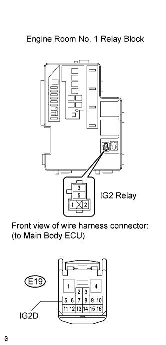 |
Remove the IG2 relay from the engine room No. 1 relay block.
Disconnect the E19 main body ECU connector.
Measure the resistance according to the value(s) in the table below.
| Tester Connection | Condition | Specified Condition |
| Relay block IG2 relay terminal 1 - E19-5 (IG2D) | Always | Below 1 Ω |
| Relay block IG2 relay terminal 2 - Body ground | Always | Below 1 Ω |
| Relay block IG2 relay terminal 1 or E19-5 (IG2D) - Body ground | Always | 10 kΩ or higher |
|
| ||||
| OK | |
|
| 9.CHECK HARNESS AND CONNECTOR (ACC RELAY - MAIN BODY ECU) |
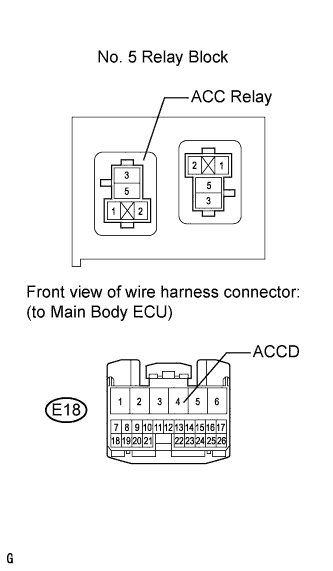 |
Remove the ACC relay from the No. 5 relay block.
Disconnect the E18 main body ECU connector.
Measure the resistance according to the value(s) in the table below.
| Tester Connection | Condition | Specified Condition |
| Relay block ACC relay terminal 1 - E18-4 (ACCD) | Always | Below 1 Ω |
| Relay block ACC relay terminal 2 - Body ground | Always | Below 1 Ω |
| Relay block ACC relay terminal 1 or E18-4 (ACCD) - Body ground | Always | 10 kΩ or higher |
|
| ||||
| OK | |
|
| 10.INSPECT ENGINE SWITCH |
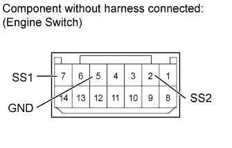 |
Remove the engine switch (Click here).
Measure the resistance according to the value(s) in the table below.
| Tester Connection | Switch Condition | Specified Condition |
| 7 (SS1) - 5 (GND) | Pushed | Below 1 Ω |
| 2 (SS2) - 5 (GND) | Pushed | Below 1 Ω |
| 7 (SS1) - 5 (GND) | Not pushed | 10 kΩ or higher |
| 2 (SS2) - 5 (GND) | Not pushed | 10 kΩ or higher |
|
| ||||
| OK | |
|
| 11.CHECK HARNESS AND CONNECTOR (MAIN BODY ECU - BATTERY AND BODY GROUND) |
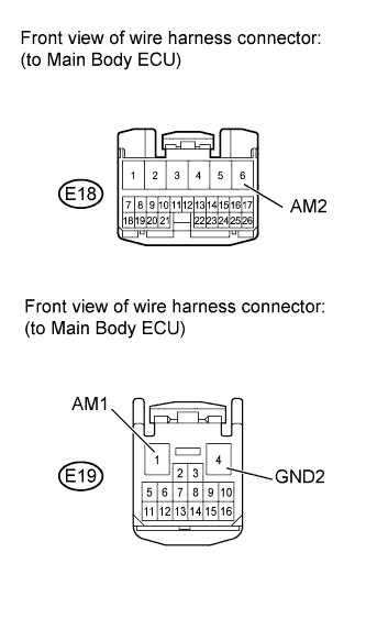 |
Disconnect the E18 and E19 main body ECU connectors.
Measure the voltage and resistance according to the value(s) in the table below.
| Tester Connection | Condition | Specified Condition |
| E19-1 (AM1) - Body ground | Always | 11 to 14 V |
| E18-6 (AM2) - Body ground | Always | 11 to 14 V |
| Tester Connection | Condition | Specified Condition |
| E19-4 (GND2) - Body ground | Always | Below 1 Ω |
|
| ||||
| OK | ||
| ||
| ||

