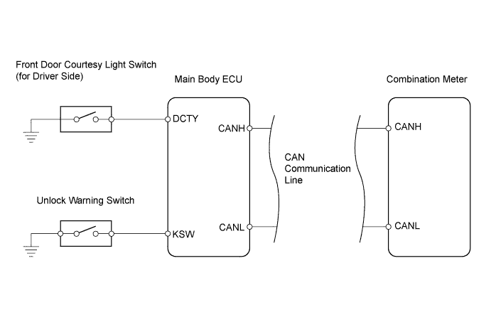
KEY REMINDER WARNING SYSTEM (w/o Entry and Start System) > Key Reminder Buzzer does not Sound |
| 1.READ VALUE USING INTELLIGENT TESTER (FRONT DOOR COURTESY LIGHT SWITCH) |
Check the Data List to ensure proper operation of the front door courtesy light switch.
| Item | Measurement Item / Display (Range) | Normal Condition | Diagnostic Note |
| D Door Courtesy SW | Driver side door courtesy switch signal / ON or OFF | ON: Driver side door is open OFF: Driver side door is closed | - |
|
| ||||
| OK | |
 |
| 2.READ VALUE USING INTELLIGENT TESTER (UNLOCK WARNING SWITCH) |
Check the Data List to ensure proper operation of the door unlock warning switch.
| Item | Measurement Item / Display (Range) | Normal Condition | Diagnostic Note |
| Key Unlock Warning SW | Unlock warning switch signal / ON or OFF | ON: Key is in ignition key cylinder OFF: No key is in ignition key cylinder | - |
|
| ||||
| NG | |
|
| 3.INSPECT UNLOCK WARNING SWITCH ASSEMBLY |
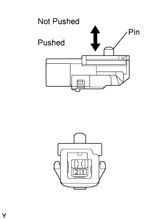 |
Remove the unlock warning switch.
Measure the resistance of the switch.
| Tester Connection | Condition | Specified Condition |
| 1 - 2 | Not pushed | 10 kΩ or higher |
| 1 - 2 | Pushed | Below 1 Ω |
|
| ||||
| OK | |
|
| 4.CHECK WIRE HARNESS (UNLOCK WARNING SWITCH - MAIN BODY ECU) |
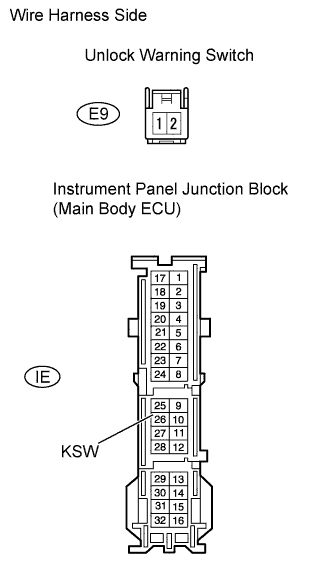 |
Disconnect the E9 switch connector.
Disconnect the IE junction block connector.
Measure the resistance between the wire harness side connectors.
| Tester Connection | Specified Condition |
| E9-1 - IE-26 (KSW) | Below 1 Ω |
| E9-2 - Body ground | Below 1 Ω |
|
| ||||
| OK | ||
 | ||
| ||
| 5.INSPECT FRONT DOOR COURTESY LIGHT SWITCH (for Driver Side) |
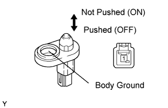 |
Remove the courtesy light switch.
Measure the resistance of the switch.
| Tester Connection | Condition | Specified Condition |
| 1 - Body ground | Not pushed (ON) | Below 1 Ω |
| 1 - Body ground | Pushed (OFF) | 10 kΩ or higher |
|
| ||||
| OK | |
|
| 6.CHECK WIRE HARNESS AND CONNECTORS (FRONT DOOR COURTESY LIGHT SWITCH - MAIN BODY ECU) |
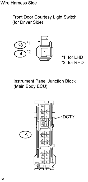 |
Disconnect the K8*1 or L4*2 switch connector.
Disconnect the IA junction block connector.
Measure the resistance between the wire harness side connectors.
| Tester Connection | Specified Condition |
| K7-1 - IA-21 (DCTY) | Below 1 Ω |
|
| ||||
| OK | ||
| ||
| ||

