 |
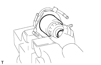
Check and clean the installation surface of the fuel filter.
FUEL FILTER > INSTALLATION |
| 1. INSTALL FUEL FILTER ELEMENT ASSEMBLY |
|
Check and clean the installation surface of the fuel filter.
Apply fuel to the gasket of a new fuel filter element.
Lightly screw the fuel filter element into place, and tighten it until the gasket comes into contact with the seat.
Tighten it an additional 3/4 turn by hand.
| 2. INSTALL LEVEL WARNING SWITCH |
Install a new O-ring to the level warning switch.
Apply fuel to the O-ring of the level warning switch.
Install the level warning switch to the fuel filter and tighten it by hand.
| 3. INSTALL FUEL FILTER ASSEMBLY |
Install the fuel filter with the bolt.
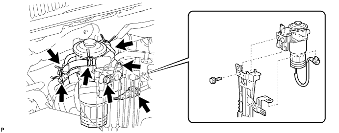
Connect the 4 hoses.
Connect the level warning switch connector.
| 4. INSTALL AIR CLEANER CASE |
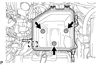 |
Attach the clamp and install the air cleaner case with the 3 bolts.
| 5. INSTALL AIR CLEANER FILTER ELEMENT SUB-ASSEMBLY |
| 6. INSTALL AIR CLEANER CAP SUB-ASSEMBLY |
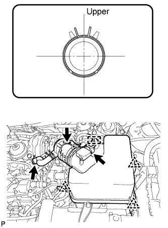 |
Connect the air cleaner hose.
Attach the 3 clips to install the air cleaner cap.
Connect the PCV hose.
Attach the clamp and connect the mass air flow meter connector.
| 7. BLEED AIR FROM FUEL SYSTEM |
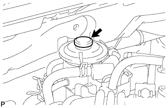 |
Using the hand pump mounted on the fuel filter cap, bleed the air from the fuel system. Continue pumping until the pump resistance increases.
Start the engine.
When the engine can be started, proceed to the next step.
If the engine cannot be started, bleed the air again using the hand pump until the hand pump resistance increases (refer to the procedures above). Then start the engine.
Turn the ignition switch off.
Connect the intelligent tester to the DLC3.
Turn the ignition switch to ON and turn the intelligent tester on.
Clear DTCs (Click here).
Start the engine.*1
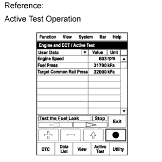 |
Enter the following menus: Powertrain / Engine and ECT / Active Test / Test the Fuel Leak.*2
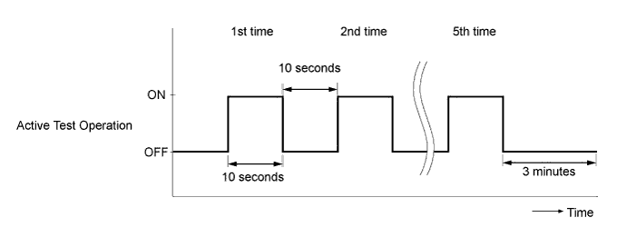
Perform the following test 5 times with on/off intervals of 10 seconds: Active Test / Test the Fuel Leak.*3
Allow the engine to idle for 3 minutes or more after performing the Active Test for the fifth time.
Enter the following menus: Powertrain / Engine and ECT / DTC.
Read Current DTCs.
When no DTCs are output, the air bleeding is completed.
If any DTCs are output, proceed to the next step.
Clear the DTCs (Click here).
Repeat steps *1 to *3.
Enter the following menus: Powertrain / Engine and ECT / DTC.
Read Current DTCs.
| 8. INSPECT FOR FUEL LEAK |
Perform Active Test.
Connect the intelligent tester to the DLC3.
Turn the ignition switch to ON.
Start the engine.
Turn the intelligent tester on.
Enter the following menus: Powertrain / Engine and ECT / Active Test.
Perform the Active Test.
| Tester Display | Test Part | Control Range | Diagnostic Notes |
| Test the Fuel Leak | Pressurizes common rail internal fuel pressure, and checks for fuel leaks | Stop/Start | Performs inspection of the high pressure fuel system.
|
| 9. INSTALL NO. 1 ENGINE COVER |
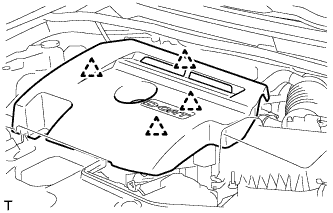 |
Attach the 4 clips to install the engine cover.