 |
Check the No. 1 output shaft for wear and damage.
OUTPUT SHAFT > INSPECTION |
| 1. INSPECT NO. 1 OUTPUT SHAFT |
|
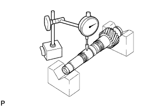
Check the No. 1 output shaft for wear and damage.
Using a dial indicator, measure the No. 1 output shaft runout.
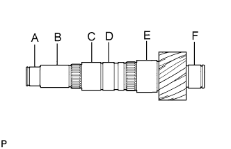 |
Using a micrometer, measure the outer diameter of the No. 1 output shaft journal surface.
| Item | Specified Condition |
| A | 32.002 to 32.018 mm (1.2600 to 1.2605 in.) |
| B | 35.984 to 36.000 mm (1.4167 to 1.4173 in.) |
| C | 41.984 to 42.000 mm (1.6530 to 1.6535 in.) |
| D | 41.989 to 42.000 mm (1.6532 to 1.6535 in.) |
| E | 46.984 to 47.000 mm (1.8498 to 1.8503 in.) |
| F | 36.002 to 36.018 mm (1.4174 to 1.4180 in.) |
| 2. INSPECT 1ST DRIVEN GEAR THRUST CLEARANCE |
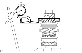 |
Using a dial indicator, measure the 1st driven gear thrust clearance.
| 3. INSPECT 1ST DRIVEN GEAR RADIAL CLEARANCE |
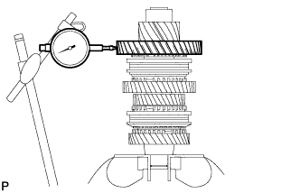 |
Using a dial indicator, measure the 1st driven gear radial clearance.
| 4. INSPECT 2ND DRIVEN GEAR THRUST CLEARANCE |
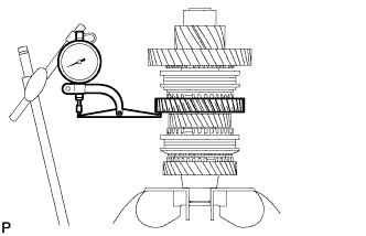 |
Using a dial indicator, measure the 2nd driven gear thrust clearance.
| 5. INSPECT 2ND DRIVEN GEAR RADIAL CLEARANCE |
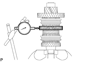 |
Using a dial indicator, measure the 2nd driven gear radial clearance.
| 6. INSPECT 3RD DRIVEN GEAR THRUST CLEARANCE |
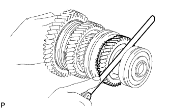 |
Using a feeler gauge, measure the 3rd driven gear thrust clearance.
| 7. INSPECT 3RD DRIVEN GEAR RADIAL CLEARANCE |
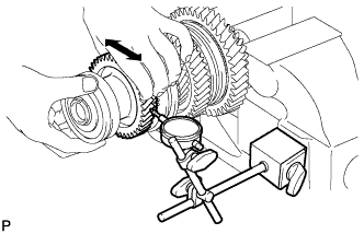 |
Using a dial indicator, measure the 3rd driven gear radial clearance.
| 8. INSPECT 4TH DRIVEN GEAR THRUST CLEARANCE |
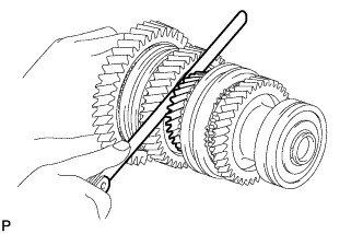 |
Using a feeler gauge, measure the 4th driven gear thrust clearance.
| 9. INSPECT 4TH DRIVEN GEAR RADIAL CLEARANCE |
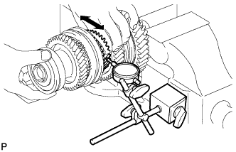 |
Using a dial indicator, measure the 4th driven gear radial clearance.
| 10. INSPECT 5TH DRIVEN GEAR THRUST CLEARANCE |
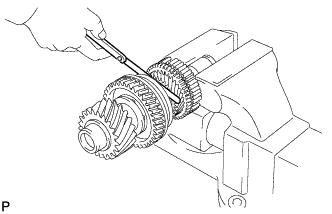 |
Using a feeler gauge, measure the 5th driven gear thrust clearance.
| 11. INSPECT 5TH DRIVEN GEAR RADIAL CLEARANCE |
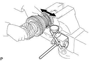 |
Using a dial indicator, measure the 5th driven gear radial clearance.
| 12. INSPECT 6TH DRIVEN GEAR THRUST CLEARANCE |
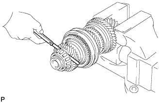 |
Using a feeler gauge, measure the 6th driven gear thrust clearance.
| 13. INSPECT 6TH DRIVEN GEAR RADIAL CLEARANCE |
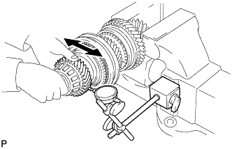 |
Using a dial indicator, measure the 6th driven gear radial clearance.
| 14. INSPECT REVERSE DRIVEN GEAR THRUST CLEARANCE |
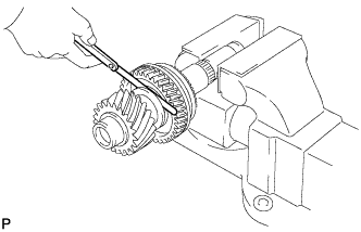 |
Using a feeler gauge, measure the reverse driven gear thrust clearance.
| 15. INSPECT REVERSE DRIVEN GEAR RADIAL CLEARANCE |
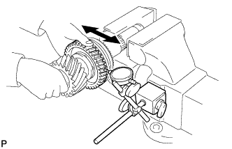 |
Using a dial indicator, measure the reverse driven gear radial clearance.
| 16. INSPECT 1ST AND 2ND SHIFT FORK SHAFT |
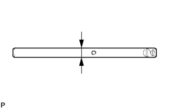 |
Using a micrometer, measure the 1st and 2nd shift fork shaft.
| 17. INSPECT 3RD AND 4TH SHIFT FORK SHAFT |
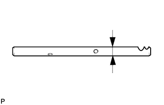 |
Using a micrometer, measure the 3rd and 4th shift fork shaft.
| 18. INSPECT 5TH AND 6TH SHIFT FORK SHAFT |
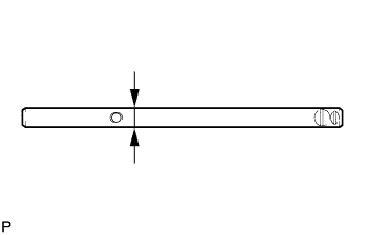 |
Using a micrometer, measure the 5th and 6th shift fork shaft.
| 19. INSPECT REVERSE SHIFT FORK SHAFT |
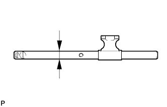 |
Using a micrometer, measure the reverse shift fork shaft.
| 20. INSPECT NO. 5 GEAR SHIFT FORK SHAFT |
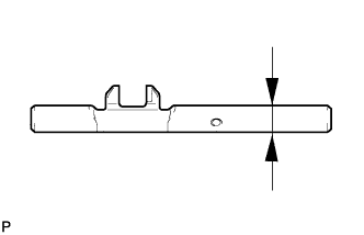 |
Using a micrometer, measure the No. 5 gear shift fork shaft.
| 21. INSPECT NO. 1 GEAR SHIFT FORK |
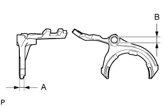 |
Using vernier caliper, measure the No. 1 gear shift fork.
| 22. INSPECT NO. 2 GEAR SHIFT FORK |
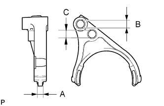 |
Using vernier caliper, measure the No. 2 gear shift fork.
| 23. INSPECT NO. 3 GEAR SHIFT FORK |
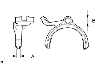 |
Using vernier caliper, measure the No. 3 gear shift fork.
| 24. INSPECT REVERSE SHIFT FORK |
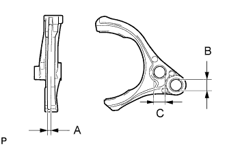 |
Using vernier caliper, measure the reverse shaft fork.
| 25. INSPECT NO. 2 GEAR SHIFT HEAD |
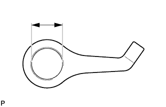 |
Using vernier caliper, measure the No. 2 gear shift head.
| 26. INSPECT NO. 3 GEAR SHIFT HEAD |
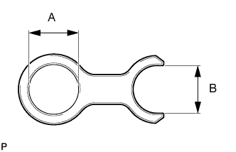 |
Using vernier caliper, measure the No. 3 gear shift head.
| 27. INSPECT 1ST DRIVEN GEAR |
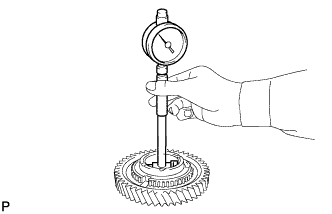 |
Using a cylinder gauge, measure the inside diameter of the 1st driven gear.
| 28. INSPECT 2ND DRIVEN GEAR |
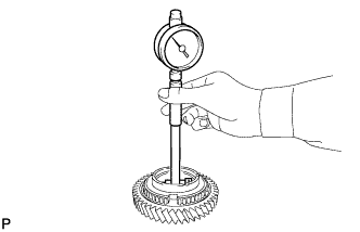 |
Using a cylinder gauge, measure the inside diameter of the 2nd driven gear.
| 29. INSPECT 3RD DRIVEN GEAR |
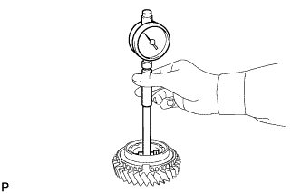 |
Using a cylinder gauge, measure the inside diameter of the 3rd driven gear.
| 30. INSPECT 4TH DRIVEN GEAR |
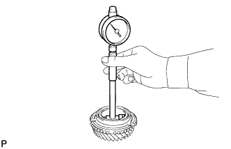 |
Using a cylinder gauge, measure the inside diameter of the 4th driven gear.
| 31. INSPECT 1ST DRIVEN GEAR SYNCHRONIZER RING SET |
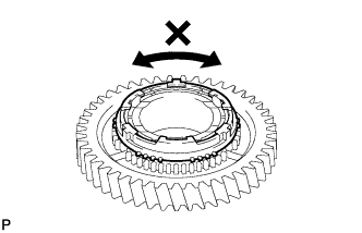 |
Check for wear and damage.
Coat the 1st driven gear cone with gear oil.
Turn the synchronizer ring in both directions while pushing it against the 1st driven gear cone and check that it locks in both directions.
If the synchronizer ring does not lock, replace the synchronizer ring.
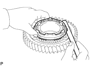 |
Using a feeler gauge, measure the clearance between the synchronizer ring back and gear spline end.
| 32. INSPECT 2ND DRIVEN GEAR SYNCHRONIZER RING SET |
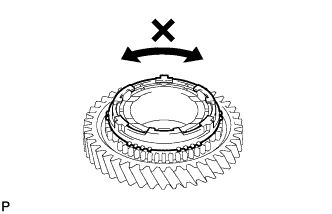 |
Check for wear and damage.
Coat the 2nd driven gear cone with gear oil.
Turn the synchronizer ring in both directions while pushing it against the 2nd driven gear cone and check that it locks in both directions.
If the synchronizer ring does not lock, replace the synchronizer ring.
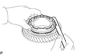 |
Using a feeler gauge, measure the clearance between the synchronizer ring back and 2nd gear spline end.
| 33. INSPECT 3RD DRIVEN GEAR SYNCHRONIZER RING SET |
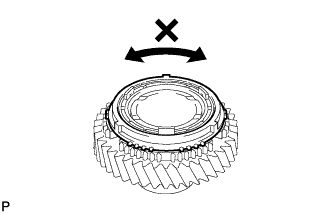 |
Check for wear and damage.
Coat the 3rd driven gear cone with gear oil.
Turn the synchronizer ring in both directions while pushing it against the 3rd driven gear cone and check that it locks in both directions.
If the synchronizer ring does not lock, replace the synchronizer ring.
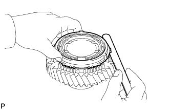 |
Using a feeler gauge, measure the clearance between the 3rd gear synchronizer ring back and spline end.
| 34. INSPECT 4TH DRIVEN GEAR SYNCHRONIZER RING SET |
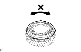 |
Check for wear and damage.
Coat the 4th driven gear cone with gear oil.
Turn the synchronizer ring in both directions while pushing it against the 4th driven gear cone and check that it locks in both directions.
If the synchronizer ring does not lock, replace the synchronizer ring.
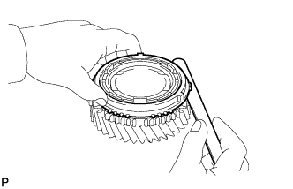 |
Using a feeler gauge, measure the clearance between the 4th gear synchronizer ring back and spline end.
| 35. INSPECT NO. 1 TRANSMISSION HUB SLEEVE |
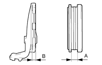 |
Using a vernier caliper, measure the clearance between the No. 1 transmission hub sleeve and the No. 1 gear shift fork.
| 36. INSPECT NO. 2 TRANSMISSION HUB SLEEVE |
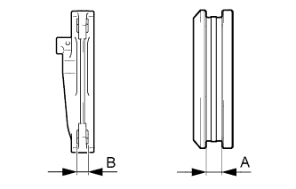 |
Using a vernier caliper, measure the clearance between the No. 2 transmission hub sleeve and the No. 2 gear shift fork.
| 37. INSPECT NO. 2 OUTPUT SHAFT |
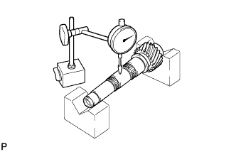 |
Check the No. 2 output shaft for wear and damage.
Using a dial indicator, check the No. 2 output shaft runout.
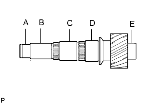 |
Using a micrometer, measure the outer diameter of the No. 2 output shaft journal surface.
| Item | Specified Condition |
| A | 32.002 to 32.018 mm (1.2600 to 1.2605 in.) |
| B | 35.984 to 36.000 mm (1.4167 to 1.4173 in.) |
| C | 41.984 to 42.000 mm (1.6530 to 1.6535 in.) |
| D | 46.984 to 47.000 mm (1.8498 to 1.8503 in.) |
| E | 35.002 to 35.018 mm (1.3781 to 1.3786 in.) |
| 38. INSPECT 5TH DRIVEN GEAR |
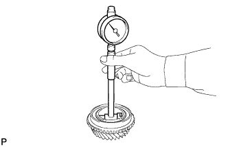 |
Using a cylinder gauge, measure the inside diameter of the 5th driven gear.
| 39. INSPECT 6TH DRIVEN GEAR |
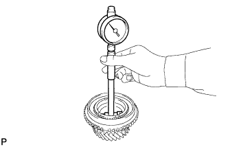 |
Using a cylinder gauge, measure the inside diameter of the 6th driven gear.
| 40. INSPECT REVERSE DRIVEN GEAR |
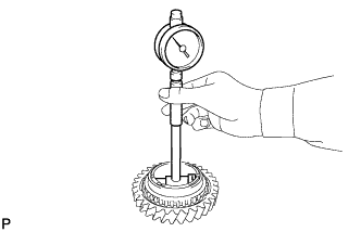 |
Using a cylinder gauge, measure the inside diameter of the reverse driven gear.
| 41. INSPECT 5TH DRIVEN SYNCHRONIZER RING SET |
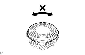 |
Check for wear and damage.
Coat the 5th driven gear cone with gear oil.
Turn the synchronizer ring in both directions while pushing it against the 5th driven gear cone and check that it locks in both directions.
If the synchronizer ring does not lock, replace the synchronizer ring.
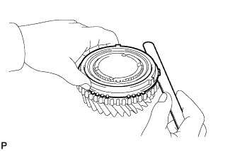 |
Using a feeler gauge, measure the clearance between the synchronizer ring back and 5th driven gear spline end.
| 42. INSPECT 6TH DRIVEN SYNCHRONIZER RING SET |
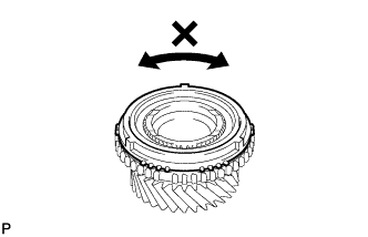 |
Check for wear and damage.
Coat the 6th driven gear cone with gear oil.
Turn the synchronizer ring in both directions while pushing it against the 6th driven gear cone and check that it locks in both directions.
If the synchronizer ring does not lock, replace the synchronizer ring.
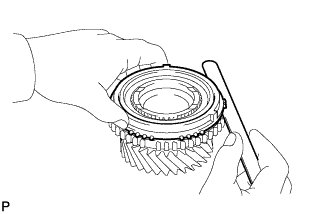 |
Using a feeler gauge, measure the clearance between the gear synchronizer ring back and 6th driven gear spline end.
| 43. INSPECT REVERSE DRIVEN SYNCHRONIZER RING SET |
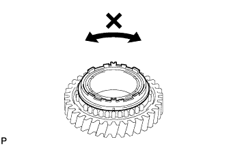 |
Check for wear and damage.
Coat the reverse driven gear cone with gear oil.
Turn the synchronizer ring in both directions while pushing it against the reverse driven gear cone and check that it locks in both directions.
If the synchronizer ring does not lock, replace the synchronizer ring.
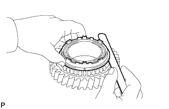 |
Using a feeler gauge, measure the clearance between the synchronizer ring back and reverse driven gear spline end.
| 44. INSPECT NO. 3 TRANSMISSION HUB SLEEVE |
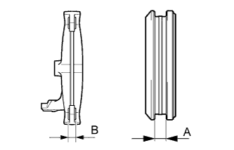 |
Using vernier caliper, measure the clearance between the No. 3 transmission hub sleeve and the No. 3 gear shift fork.
| 45. INSPECT NO. 4 TRANSMISSION HUB SLEEVE |
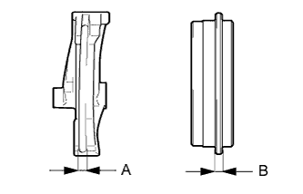 |
Using vernier caliper, measure the clearance between the No. 4 transmission hub sleeve and the reverse shift fork.