 |
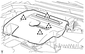
Detach the 4 clips and remove the engine cover.
- NOTICE:
- Attempting to disengage both front and rear clips at the same time may cause the cover to break.
FUEL SUPPLY PUMP > REMOVAL |
| 1. DISCONNECT CABLE FROM NEGATIVE BATTERY TERMINAL |
| 2. REMOVE NO. 1 ENGINE COVER |
|
Detach the 4 clips and remove the engine cover.
| 3. REMOVE AIR CLEANER CAP SUB-ASSEMBLY |
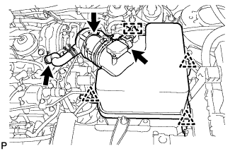 |
Detach the clamp and disconnect the mass air flow meter connector.
Disconnect the PCV hose.
Disconnect the air cleaner hose.
Detach the 3 clips and remove the air cleaner cap.
| 4. REMOVE AIR CLEANER FILTER ELEMENT SUB-ASSEMBLY |
| 5. REMOVE AIR CLEANER CASE |
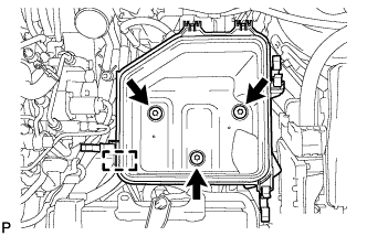 |
Detach the clamp.
Remove the 3 bolts and air cleaner case.
| 6. REMOVE NO. 3 FUEL HOSE |
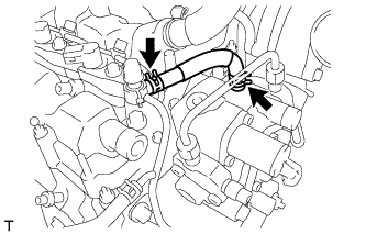 |
Using pliers, grip the claws of the 2 clips and slide the 2 clips to remove the No. 3 fuel hose.
| 7. REMOVE NO. 1 FUEL HOSE |
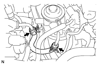 |
Using pliers, grip the claws of the 2 clips and slide the 2 clips to remove the No. 1 fuel hose.
| 8. REMOVE FUEL INLET PIPE SUB-ASSEMBLY |
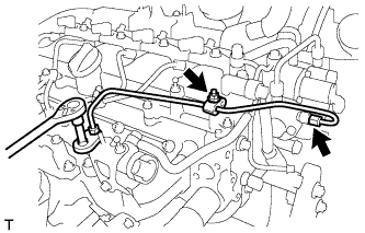 |
Remove the nut and 2 clamps.
Using a 14 mm union nut wrench, remove the fuel inlet pipe.
| 9. REMOVE FUEL HOSE PROTECTOR (for DPF) |
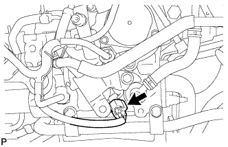 |
Disconnect the connector.
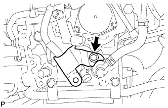 |
Remove the bolt and fuel hose protector.
| 10. REMOVE FUEL TUBE SUB-ASSEMBLY (for DPF) |
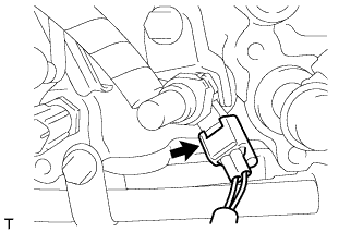 |
Disconnect the exhaust fuel addition injector connector.
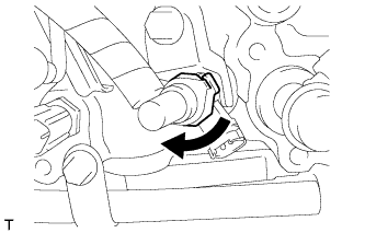 |
Turn the retainer as shown in the illustration.
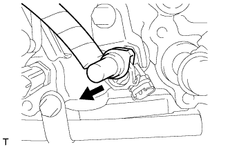 |
Disconnect the fuel tube from the exhaust fuel addition injector.
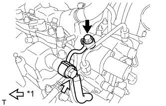 |
Remove the check valve and gasket.
| *1 | Check Valve |
Remove the union bolt, gasket and fuel tube.
| 11. REMOVE NO. 2 FUEL PIPE (for CCo) |
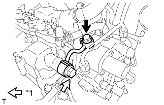 |
Remove the check valve and gasket.
| *1 | Check Valve |
Remove the union bolt, gasket and fuel pipe.
| 12. REMOVE FUEL SUPPLY PUMP ASSEMBLY |
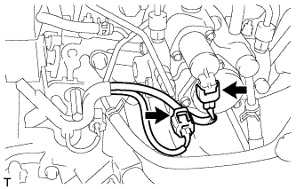 |
Disconnect the fuel temperature sensor connector.
Disconnect the suction control valve connector.
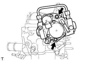 |
Remove the 2 bolts, supply pump and supply pump drive coupling.
Remove the O-ring from the supply pump.