Home › ENGINE · 2AD-FTV › STARTING › STARTER

STARTER > INSPECTION

for Preparation Click here


1. INSPECT STARTER ASSEMBLY

NOTICE:
The following tests must be performed for no longer than 5 seconds to prevent the coil from burning out.


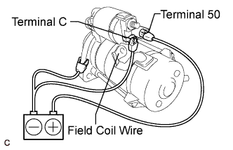
    A165168E01
  1. Perform the pull-in test.

    1. Disconnect the field coil wire from terminal C.

    2. Connect the battery to the magnetic switch as shown in the illustration. Check that the clutch pinion gear moves outward.
      If the clutch pinion gear does not move outward, replace the starter magnetic switch assembly.
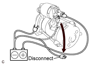


    A165169E01
  1. Perform the holding test.

    1. Disconnect the negative (-) terminal lead from terminal C with the condition specified in the pull-in test above being maintained. Check that the pinion gear remains out.
      If the clutch pinion gear moves inward, replace the starter magnetic switch assembly.
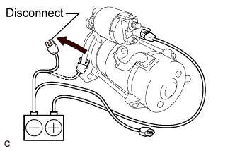


    A165170E01
  1. Inspect the clutch pinion gear return.

    1. Disconnect the negative (-) lead from the starter body. Check that the clutch pinion gear moves inward.
      If the clutch pinion gear does not move inward, replace the starter magnetic switch assembly.
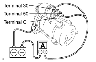


    A165171E01
  1. Perform the no-load performance test.

    1. Connect the field coil wire to terminal C with the nut. Make sure that the lead is not grounded.

      Torque:
      6.5 N*m{ 66 kgf*cm , 57 in.*lbf }

    2. Clamp the starter in a vise between aluminum plates.

    3. Connect the battery and an ammeter to the starter as shown in the illustration.

    4. Check that the starter rotates smoothly and steadily while the pinion gear is moving out. Then measure the current.

      Standard current:
      190 A or less at 11.5 V

      If the result is not as specified, replace the starter assembly.


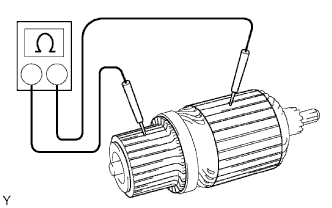
2. INSPECT STARTER ARMATURE ASSEMBLY


    A086442E04
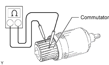
  1. Inspect the commutator for an open circuit.

    1. Measure the resistance according to the value(s) in the table below.

      Standard Resistance:
      Tester Connection
      Condition
      Specified Condition
      Commutator - Commutator
      Always
      Below 1 Ω

      If the result is not as specified, replace the armature assembly.


    A086443E01
  1. Inspect the commutator for a short circuit.

    1. Measure the resistance according to the value(s) in the table below.

      Standard Resistance:
      Tester Connection
      Condition
      Specified Condition
      Commutator - Armature coil core
      Always
      10 kΩ or higher

      If the result is not as specified, replace the armature assembly.


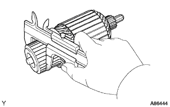
    A086444
  1. Using vernier calipers, measure the commutator diameter.

    Standard diameter:
    35.0 mm (1.378 in.)

    Minimum diameter:
    34.0 mm (1.339 in.)

    If the diameter is less than the minimum, replace the armature assembly.


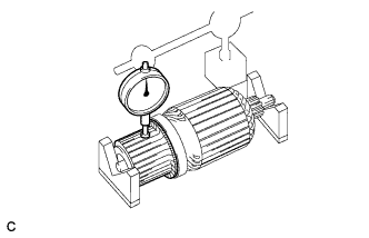
    A166866
  1. Using a dial indicator, measure the commutator runout.

    Maximum commutator runout:
    0.05 mm (0.0020 in.)

    If the commutator runout is greater than the maximum, correct it using a lathe.


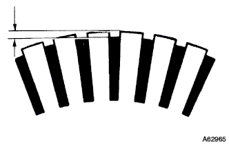
    A062965
  1. Measure the undercut depth of the commutator.

    Standard undercut depth:
    0.7 mm (0.028 in.)

    Minimum undercut depth:
    0.2 mm (0.008 in.)

    If the undercut depth is less than the minimum, increase the depth using a hacksaw blade.

  1. Check the surface of the commutator for dirt or burns.
    If the surface is dirty or burnt, smooth it with 400-grit sandpaper or lathe it.


3. INSPECT STARTER YOKE ASSEMBLY


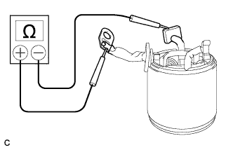
    A165175
  1. Inspect the field coil for an open circuit.

    1. Measure the resistance according to the value(s) in the table below.

      Standard Resistance:
      Tester Connection
      Condition
      Specified Condition
      Terminal C wire - Brushes
      Always
      Below 1 Ω

      If the result is not as specified, repair or replace the yoke assembly.


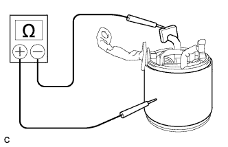
    A165176
  1. Check if the field coil is grounded.

    1. Measure the resistance according to the value(s) in the table below.

      Standard Resistance:
      Tester Connection
      Condition
      Specified Condition
      Terminal C wire - Starter yoke body
      Always
      10 kΩ or higher

      If the result is not as specified, repair or replace the yoke assembly.


4. INSPECT BRUSH


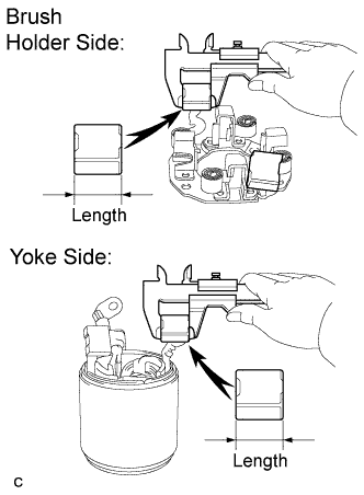
    A165177E01
  1. Using vernier calipers, measure the brush length.

    Standard length:
    15 mm (0.591 in.)

    Minimum length:
    9.0 mm (0.354 in.)

    If the brush length is less than the minimum, replace the brush holder and starter yoke assembly.


5. INSPECT STARTER BRUSH HOLDER ASSEMBLY


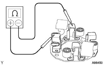
    A086450
  1. Inspect the insulation.

    1. Measure the resistance according to the value(s) in the table below.

      Standard Resistance:
      Tester Connection
      Condition
      Specified Condition
      Positive brush holder - Negative brush holder
      Always
      10 kΩ or higher

      If the result is not as specified, replace the brush holder assembly.


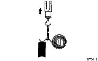
  1. Inspect the load of the brush spring.


      ST00019
    1. Take the pull scale reading immediately after the brush spring separates from the brush.

      Standard spring load:
      22 to 28 N (2 to 3 kgf, 4.8 to 6.2 lbf)

      Minimum spring load:
      12 N (1 kgf, 2.8 lbf)

      If the spring load is less than the minimum, replace the brush springs.


6. INSPECT STARTER CENTER BEARING CLUTCH SUB-ASSEMBLY
  1. Check the gear teeth of the planetary gears and starter center bearing clutch for wear or damage.
    If any planetary gear is damaged, replace the planetary gear assembly.
    If any gear of the starter center bearing clutch is damaged, replace the starter center bearing clutch sub-assembly.


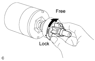
    A165178E01
  1. Check the movement of the clutch pinion gear.

    1. Rotate the clutch pinion gear clockwise and check that it turns freely.

    2. Try to rotate the clutch pinion gear counterclockwise and check that it locks.
      If the clutch pinion gear cannot be turned clockwise smoothly, or does not lock in the counterclockwise direction, replace the starter center bearing clutch sub-assembly.


7. INSPECT STARTER MAGNETIC SWITCH ASSEMBLY


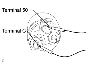
    A165172E01
  1. Check the pull-in coil for open circuits.

    1. Measure the resistance according to the value(s) in the table below.

      Standard Resistance:
      Tester Connection
      Condition
      Specified Condition
      Terminal 50 - Terminal C
      Always
      Below 1 Ω

      If the result is not as specified, replace the starter magnetic switch assembly.


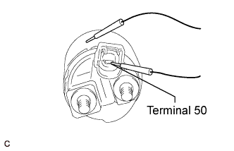
    A165173E01
  1. Check the hold-in coil for an open circuit.

    1. Measure the resistance according to the value(s) in the table below.

      Standard Resistance:
      Tester Connection
      Condition
      Specified Condition
      Terminal 50 - Switch body
      Always
      Below 2 Ω

      If the result is not as specified, replace the starter magnetic switch assembly.