 |
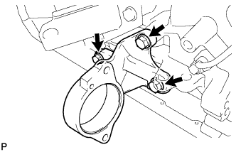
Install the bearing bracket with the 3 bolts.
- Torque:
- 64 N*m{ 650 kgf*cm , 47 ft.*lbf }
ENGINE UNIT > INSTALLATION |
| 1. INSTALL DRIVE SHAFT BEARING BRACKET |
|
Install the bearing bracket with the 3 bolts.
| 2. INSTALL EXHAUST MANIFOLD WITH TURBOCHARGER SUB-ASSEMBLY |
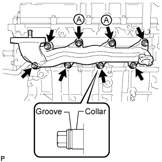 |
Temporarily install a new gasket, and the exhaust manifold and 2 collars with the 2 nuts labeled A. Tighten the nuts until the mating surface of the exhaust manifold contacts the cylinder head.
Temporarily install the 6 collars and 6 nuts.
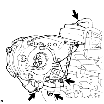 |
Install a new gasket and the turbocharger with 3 new nuts.
Connect the vacuum hose.
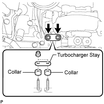 |
Install the 2 collars and a new turbocharger stay with the 2 nuts.
Tighten the 8 nuts of the exhaust manifold.
| 3. INSTALL NO. 2 TURBO OIL PIPE |
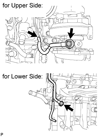 |
Install the No. 2 turbo oil pipe and 2 new gaskets with the 2 union bolts.
Connect the vacuum hose.
| 4. INSTALL NO. 2 TURBO WATER PIPE SUB-ASSEMBLY |
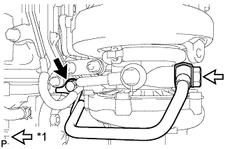 |
Install the No. 2 turbo water pipe and a new gasket with the union bolt and bolt.
| *1 | Union Bolt |
| 5. INSTALL NO. 5 WATER BY-PASS PIPE |
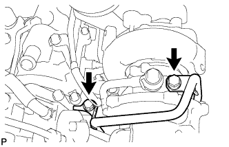 |
Install the No. 5 water by-pass pipe with the 2 bolts.
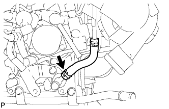
| 6. CONNECT NO. 3 WATER BY-PASS HOSE |
 |
| 7. INSTALL NO. 1 TURBO WATER PIPE SUB-ASSEMBLY |
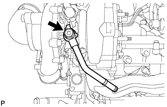 |
Install the No. 1 turbo water pipe and a new gasket with the union bolt.
| 8. INSTALL NO. 1 TURBO INSULATOR |
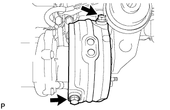 |
Install the No. 1 turbo insulator with the 2 bolts.
| 9. INSTALL TURBO OIL OUTLET PIPE |
Install 2 new gaskets to the turbo oil outlet pipe.
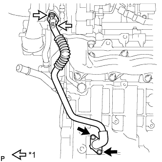 |
Install the turbo oil outlet pipe with the 2 bolts and 2 nuts.
| *1 | Nut |
| 10. INSTALL EGR COOLER WITH PIPE ASSEMBLY |
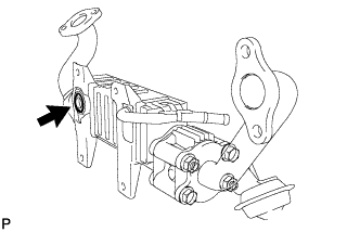 |
Install a new O-ring to the EGR cooler with pipe.
Install a new gasket to the EGR cooler and a new gasket to the No. 1 EGR pipe.
Temporarily install the EGR cooler with pipe with the 6 bolts and 2 nuts labeled A, B and C.
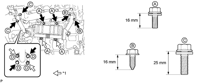
| *1 | Nut |
| Item | Length |
| Bolt A | 16 mm (0.630 in.) |
| Bolt B | 16 mm (0.630 in.) |
| Bolt C | 25 mm (0.984 in.) |
Tighten the 2 bolts and 2 nuts labeled A shown in the illustration.
Tighten the 2 bolts labeled B shown in the illustration.
Tighten the 2 bolts labeled C shown in the illustration.
Tighten the 2 bolts and 2 nuts labeled D shown in the illustration.
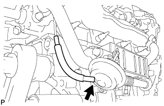 |
Connect the vacuum hose.
| 11. INSTALL NO. 2 WATER BY-PASS HOSE |
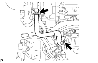 |
| 12. INSTALL EXHAUST MANIFOLD CONVERTER SUB-ASSEMBLY (for CCo) |
Install a new gasket to the turbocharger.
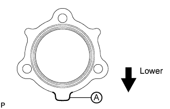 |
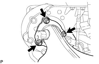 |
Temporarily install the exhaust manifold converter with the 3 nuts.
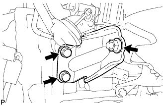 |
Temporarily install the No. 2 exhaust manifold stay with the 2 bolts and nut.
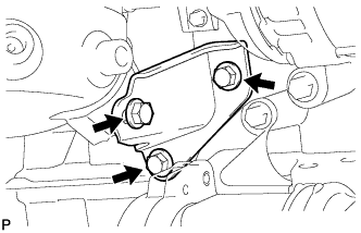 |
Temporarily install the No. 2 manifold stay with the 3 bolts.
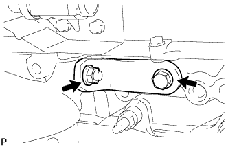 |
Temporarily install the manifold stay with the bolt and nut.
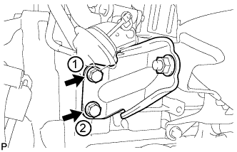 |
Tighten the 2 bolts of the No. 2 exhaust manifold stay in the order shown in the illustration.
|
Tighten the 3 nuts of the exhaust manifold converter.
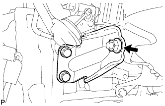 |
Tighten the nut of the No. 2 exhaust manifold stay.
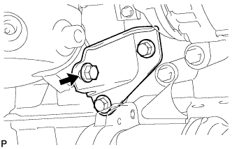 |
Tighten the bolt of the No. 2 manifold stay shown in the illustration.
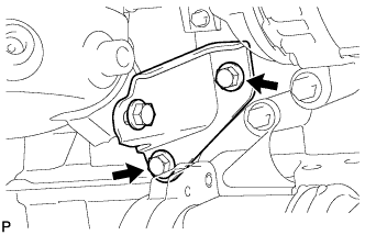 |
Tighten the 2 bolts of the No. 2 manifold stay shown in the illustration.
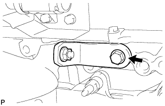 |
Tighten the bolt of the manifold stay.
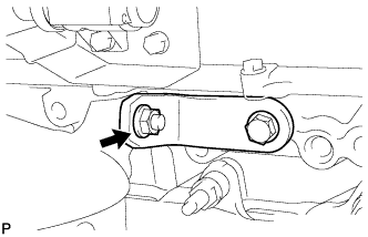 |
Tighten the nut of the manifold stay.
| 13. INSTALL EXHAUST MANIFOLD CONVERTER SUB-ASSEMBLY (for DPF) |
Install a new gasket to the turbocharger.
|
|
Temporarily install the exhaust manifold converter with the 3 nuts.
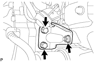 |
Temporarily install the No. 2 exhaust manifold stay with the 2 bolts and nut.
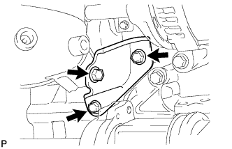 |
Temporarily install the No. 2 manifold stay with the 3 bolts.
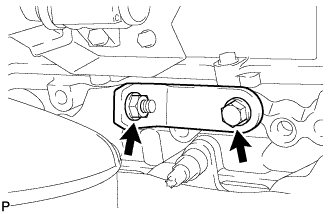 |
Temporarily install the manifold stay with the bolt and nut.
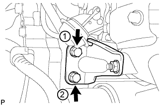 |
Tighten the 2 bolts of the No. 2 exhaust manifold stay in the order shown in the illustration.
|
Tighten the 3 nuts of the exhaust manifold converter.
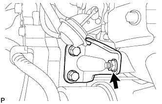 |
Tighten the nut of the No. 2 exhaust manifold stay.
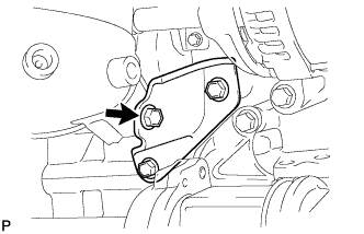 |
Tighten the bolt of the No. 2 manifold stay shown in the illustration.
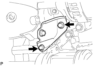 |
Tighten the 2 bolts of the No. 2 manifold stay shown in the illustration.
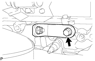 |
Tighten the bolt of the manifold stay.
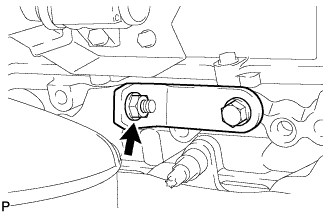 |
Tighten the nut of the manifold stay.
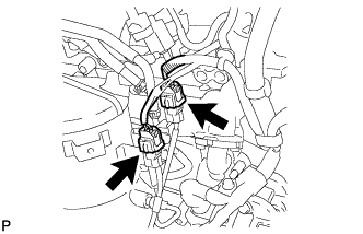 |
Connect the 2 connectors.
| 14. INSTALL NO. 1 MANIFOLD CONVERTER INSULATOR (for CCo) |
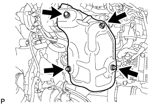 |
Install the insulator with the 4 bolts.
| 15. INSTALL NO. 1 MANIFOLD CONVERTER INSULATOR (for DPF) |
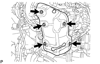 |
Install the insulator with the 5 bolts.
| 16. INSTALL VACUUM SWITCHING VALVE BRACKET |
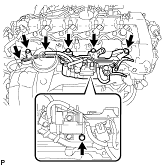 |
Install the vacuum switching valve bracket with the 5 bolts.
Connect the 2 vacuum hoses.
| 17. INSTALL NO. 1 VACUUM TRANSMITTING PIPE SUB-ASSEMBLY |
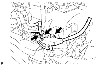 |
Install the No. 1 vacuum transmitting pipe with the bolt.
Connect the 2 vacuum hoses.
| 18. INSTALL NO. 1 TURBO OIL PIPE |
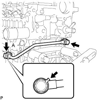 |
Install the oil pipe and 2 new gaskets with the 2 union bolts.
| 19. INSTALL NO. 3 WATER BY-PASS PIPE |
Apply soapy water to a new O-ring and install it to the by-pass pipe.
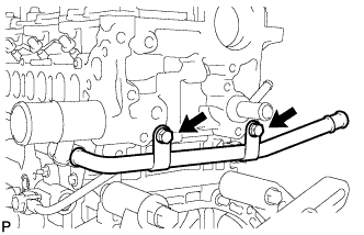 |
Install the by-pass pipe with the 2 bolts.
| 20. INSTALL SUPPLY PUMP ASSEMBLY |
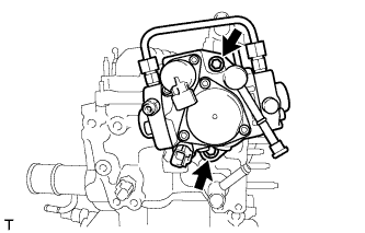 |
Install a new O-ring to the supply pump.
Install the supply pump drive coupling.
Install the supply pump with the 2 bolts.
| 21. INSTALL NO. 3 FUEL HOSE |
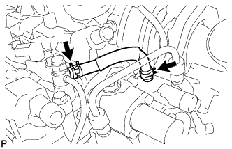 |
| 22. INSTALL FUEL INJECTOR SEAL (for DPF) |
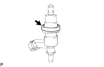 |
Install a new fuel injector seal to the exhaust fuel addition injector.
| 23. INSTALL EXHAUST FUEL ADDITION INJECTOR ASSEMBLY (for DPF) |
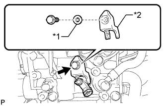 |
Install a new gasket, the exhaust fuel addition injector and nozzle holder clamp with the washer and bolt.
| *1 | Washer |
| *2 | Nozzle Holder Clamp |
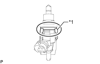 |
| *1 | Nozzle Holder Clamp |
| 24. INSTALL NO. 2 FUEL PIPE (for CCo) |
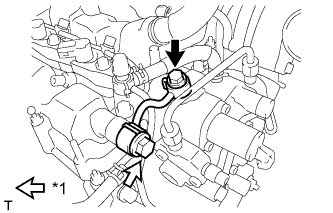 |
Temporarily install the fuel pipe with 2 new gaskets, the check valve and union bolt.
| *1 | Check Valve |
Tighten the check valve.
Tighten the union bolt.
| 25. INSTALL FUEL TUBE SUB-ASSEMBLY (for DPF) |
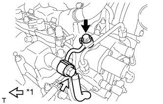 |
Temporarily install the fuel tube with 2 new gaskets, the check valve and union bolt.
| *1 | Check Valve |
Tighten the check valve.
Tighten the union bolt.
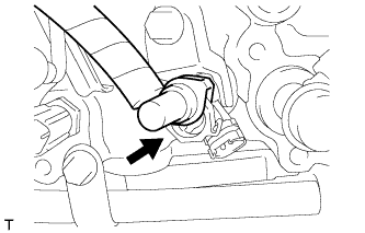 |
Insert the fuel tube connector onto the injector.
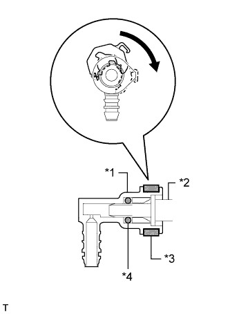 |
Turn the retainer in the direction indicated by the arrow until it makes a "click" sound.
| *1 | Fuel Tube Connector |
| *2 | Injector |
| *3 | Retainer |
| *4 | O-Ring |
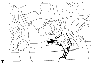 |
Connect the exhaust fuel addition injector connector.
| 26. INSTALL FUEL HOSE PROTECTOR (for DPF) |
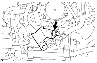 |
Install the fuel hose protector with the bolt.
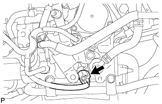 |
Connect the connector.
| 27. INSTALL NO. 2 WATER BY-PASS PIPE |
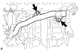 |
Install a new No. 2 water by-pass pipe with the 2 bolts.
| 28. INSTALL NO. 4 WATER BY-PASS HOSE |
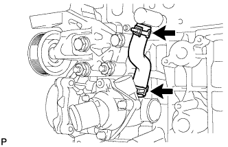 |
Install the No. 4 water by-pass hose.
| 29. INSTALL NO. 8 WATER BY-PASS HOSE |
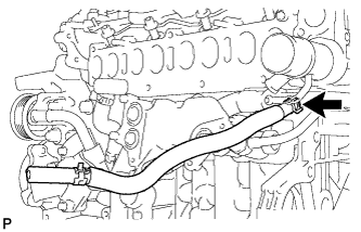 |
Install the No. 8 water by-pass hose.
| 30. INSTALL NO. 6 WATER BY-PASS HOSE |
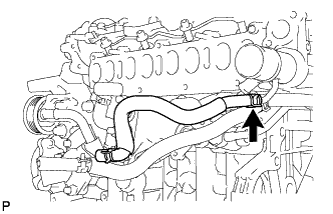 |
Install the No. 6 water by-pass hose.
| 31. INSTALL NO. 1 WATER BY-PASS HOSE |
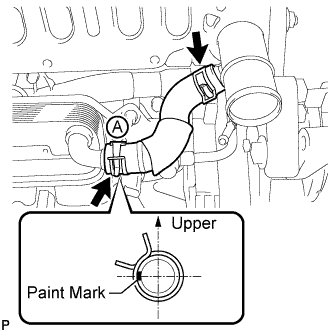 |
| 32. INSTALL NO. 1 CYLINDER BLOCK INSULATOR |
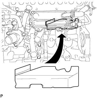 |
Install the No. 1 cylinder block insulator to the cylinder block.
| 33. INSTALL GLOW PLUG ASSEMBLY |
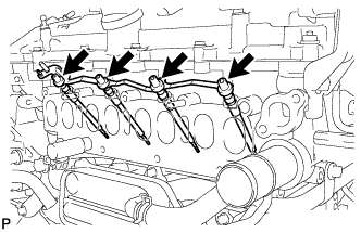 |
Using a 10 mm deep socket wrench, install the 4 glow plugs.
Install the glow plug connector with the 4 nuts.
Install the 4 grommets.
| 34. INSTALL INTAKE MANIFOLD |
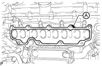 |
Install a new gasket to the cylinder head.
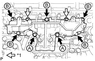 |
Install the intake manifold with the 7 bolts and 2 nuts.
| *1 | Nut |
| Item | Length |
| Bolt A | 90 mm (3.54 in.) |
| Bolt B | 25 mm (0.984 in.) |
| 35. INSTALL NO. 2 INTAKE MANIFOLD |
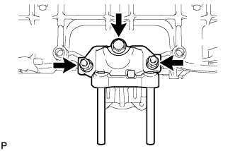 |
Install a new gasket and the No. 2 intake manifold with the bolt and 2 nuts.
| 36. INSTALL ENGINE COVER BRACKET |
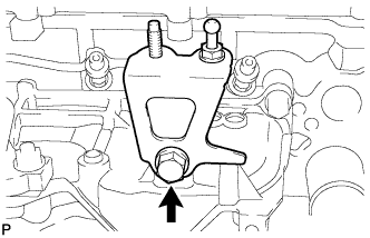 |
Install the engine cover bracket with the bolt.
| 37. INSTALL GAS FILTER BRACKET |
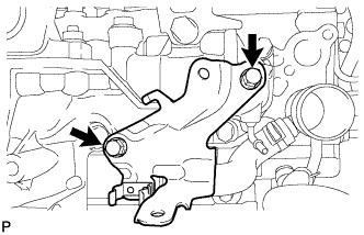 |
Install the gas filter bracket with the 2 bolts.
| 38. INSTALL NO. 1 GAS FILTER |
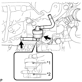 |
Install the No. 1 gas filter to the gas filter bracket.
| *1 | Protrusion |
| *2 | Groove |
Connect the vacuum hose.
| 39. REMOVE DIESEL TURBO PRESSURE SENSOR |
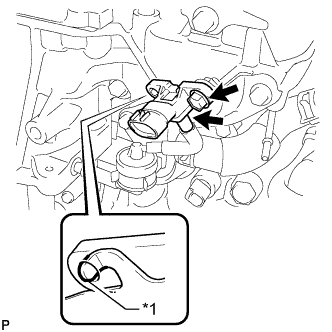 |
Install the sensor with the bolt.
| *1 | Protrusion |
Connect the vacuum hose.
| 40. INSTALL INTAKE MANIFOLD INSULATOR |
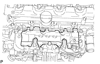 |
Install the intake manifold insulator to the intake manifold.
| 41. INSTALL COMMON RAIL ASSEMBLY |
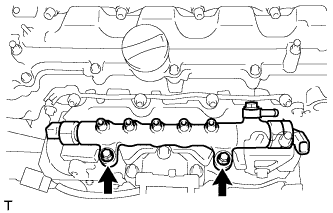 |
Install the common rail with the 2 bolts.
| 42. INSTALL NO. 4 FUEL HOSE |
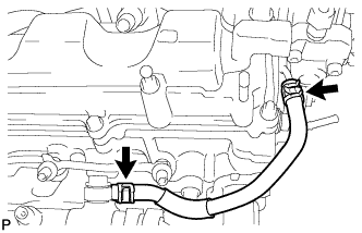 |
| 43. INSTALL INJECTION PIPE |
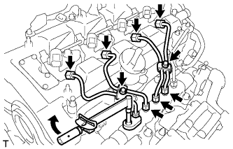 |
Using a 14 mm union nut wrench, tighten the 4 nuts at the common rail end of the injection pipes.
Using a 14 mm union nut wrench, tighten the 4 nuts at the injector end of the injection pipes.
Install the 4 injection pipe clamps with the 2 bolts.
| 44. INSTALL FUEL INLET PIPE SUB-ASSEMBLY |
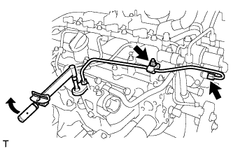 |
Temporarily install the fuel inlet pipe with the 2 clamps and nut.
Using a 14 mm union nut wrench, first tighten the nut at the common rail end of the fuel inlet pipe.
Using a 14 mm union nut wrench, tighten the nut at the supply pump end of the fuel inlet pipe.
Tighten the No. 2 injection pipe clamp nut.
| 45. INSTALL ENGINE OIL LEVEL DIPSTICK GUIDE |
Install a new O-ring to the engine oil level dipstick guide.
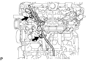 |
Install the engine oil level dipstick guide with the 2 bolts.
Install the engine oil level dipstick.
| 46. REMOVE ELECTRIC EGR CONTROL VALVE ASSEMBLY |
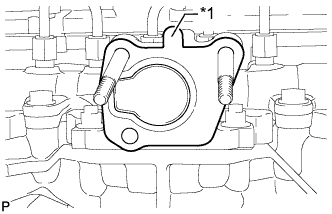 |
Install a new gasket.
| *1 | Protrusion |
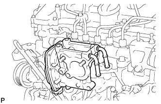 |
Install the electric EGR control valve.
| 47. INSTALL NO. 2 EGR PIPE SUB-ASSEMBLY |
Install a new gasket to the electric EGR control valve.
Install a new gasket to the No. 2 EGR pipe.
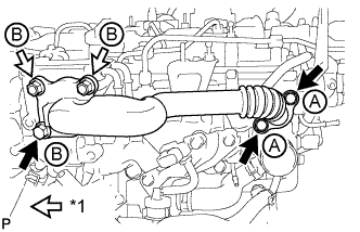 |
Temporarily install the No. 2 EGR pipe with the 3 bolts and 2 nuts.
| *1 | Nut |
| Item | Length |
| Bolt A | 25 mm (0.984 in.) |
| Bolt B | 70 mm (2.76 in.) |
Tighten the 2 bolts labeled A shown in the illustration.
Tighten the bolt and 2 nuts labeled B shown in the illustration.
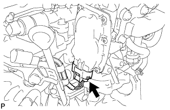 |
Connect the electric EGR control valve connector.
| 48. INSTALL EGR VALVE BRACKET |
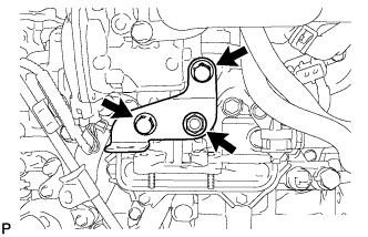 |
Install the EGR valve brackets with the 3 bolt.
| 49. CONNECT NO. 8 WATER BY-PASS HOSE |
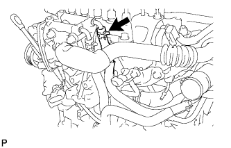 |
| 50. INSTALL NO. 7 WATER BY-PASS HOSE |
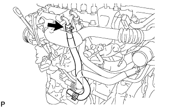 |
| 51. INSTALL DIESEL THROTTLE BODY ASSEMBLY |
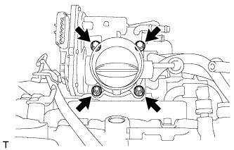 |
Install a new gasket and the diesel throttle body with the 2 bolts and 2 nuts.
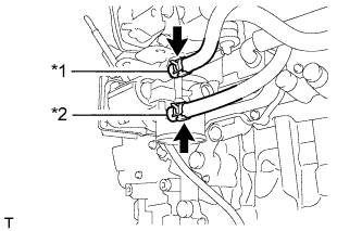 |
Connect the No. 6 and No. 7 water by-pass hoses.
| *1 | No. 6 Water By-pass Hose |
| *2 | No. 7 Water By-pass Hose |
| 52. INSTALL VACUUM PUMP ASSEMBLY |
Apply a light coat of engine oil to 2 new O-rings.
Install 2 new O-rings to the vacuum pump.
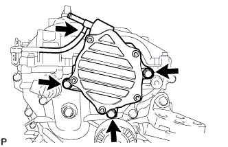 |
Install the vacuum pump with 3 new bolts.
Connect the vacuum hose.
| 53. INSTALL V-RIBBED BELT TENSIONER ASSEMBLY |
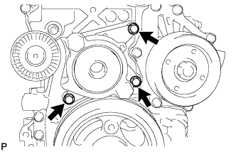 |
Install the belt tensioner with the 3 bolts.
| 54. INSTALL ENGINE MOUNTING BRACKET |
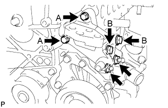 |
Set the mounting bracket on the engine.
Temporarily install the 2 bolts labeled B and 2 nuts.
Install the 2 bolts labeled A.
Tighten the 2 bolts labeled B and 2 nuts.
Install the stud bolt to the engine mounting bracket.
| 55. INSTALL NO. 4 WATER BY-PASS PIPE |
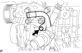 |
Install a new O-ring to the No. 4 water by-pass pipe.
Install the No. 4 water by-pass pipe with the bolt.
| 56. INSTALL NO. 1 IDLER PULLEY SUB-ASSEMBLY |
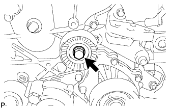 |
Install the idler pulley with the bolt.
| 57. INSTALL IDLER PULLEY COVER PLATE |
Install the idler pulley cover plate.
| 58. INSTALL NO. 2 IDLER PULLEY SUB-ASSEMBLY |
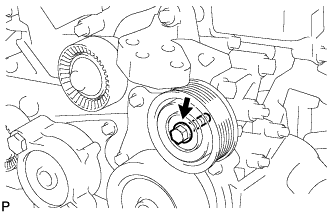 |
Install the idler pulley and plate with the bolt.
| 59. INSTALL GENERATOR ASSEMBLY |
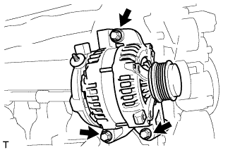 |
Install the generator with the 3 bolts.
| 60. INSTALL COMPRESSOR STAY |
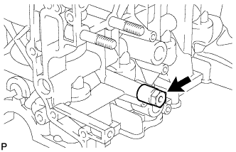 |
Install the compressor stay to the cylinder block.
| 61. INSTALL COOLER COMPRESSOR ASSEMBLY |
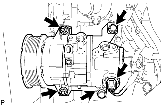 |
Using an E8 "TORX" socket wrench, connect the compressor with the 2 stud bolts.
Install the 2 bolts and 2 nuts.
Connect the connector.
| 62. INSTALL FAN AND GENERATOR V BELT |
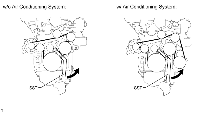
Using SST and a 22 mm wrench, rotate the tensioner pulley counterclockwise, and then install the fan and generator V belt.