CYLINDER HEAD > REASSEMBLY |
| 1. INSTALL NO. 1 WATER BY-PASS PIPE |
|
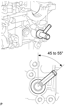
Apply adhesive to a new No. 1 water by-pass pipe.
Install the No. 1 water by-pass pipe as shown in the illustration.
| 2. INSTALL WATER OUTLET |
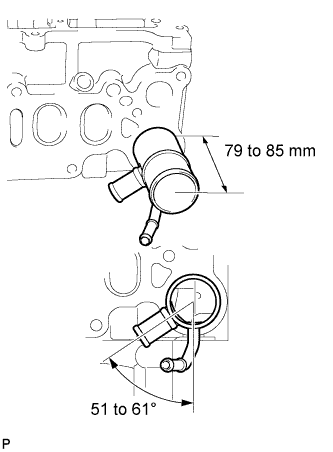 |
Apply adhesive to a new water outlet.
Install the water outlet.
| 3. INSTALL ELBOW |
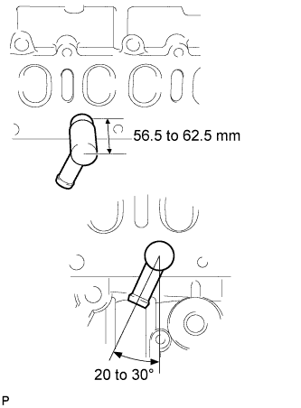 |
Apply adhesive to a new elbow.
Install the elbow.
| 4. INSTALL VALVE SPRING SEAT PLATE WASHER |
Install the valve spring seat washer to the cylinder head.
| 5. INSTALL VALVE STEM OIL SEAL |
Apply a light coat of engine oil to a new valve stem oil seal.
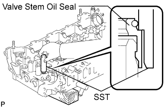 |
Using SST, push in the valve stem oil seal.
| 6. INSTALL INTAKE VALVE |
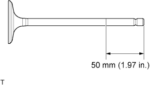 |
Apply plenty of engine oil to the tip area of the intake valve shown in the illustration.
Place the cylinder head on a wooden block.
Install the intake valve, inner compression spring and valve spring retainer to the cylinder head.
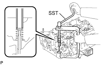 |
Using SST, compress the inner compression spring and place the valve spring retainer lock around the valve stem.
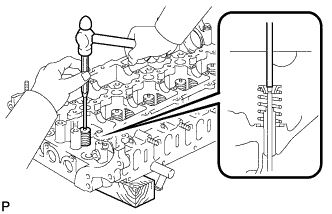 |
Using a 5 mm pin punch and plastic-faced hammer, lightly tap the valve stem tip to ensure a proper fit.
| 7. INSTALL EXHAUST VALVE |
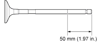 |
Apply plenty of engine oil to the tip area of the exhaust valve shown in the illustration.
Place the cylinder head on a wooden block.
Install the exhaust valve, inner compression spring and valve spring retainer to the cylinder head.
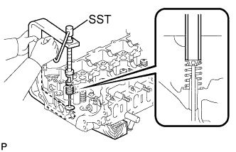 |
Using SST, compress the inner compression spring and place the valve spring retainer lock around the valve stem.
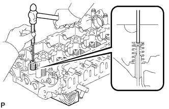 |
Using a 5 mm pin punch and plastic-faced hammer, lightly tap the valve stem tip to ensure a proper fit.