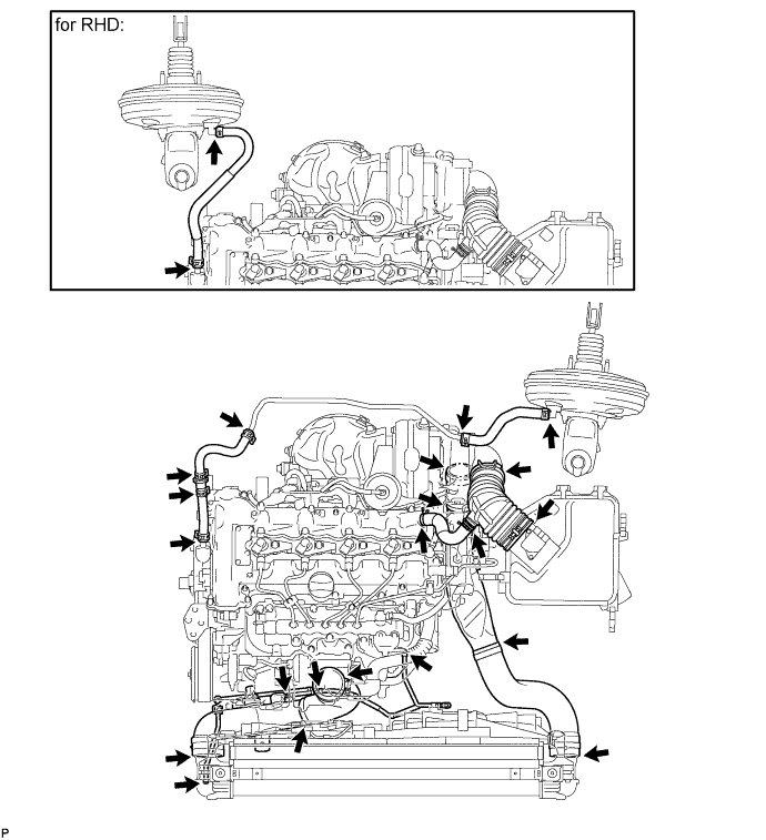
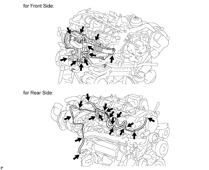
Check that there is no air suction or leaks at the points shown in the illustration.
- For engine room area:
- For engine area:
INTAKE SYSTEM > ON-VEHICLE INSPECTION |
| 1. INSPECT INTAKE SYSTEM |
Check that there is no air suction or leaks at the points shown in the illustration.
| 2. CHECK INTAKE AIR CONTROL SYSTEM |
Check for leakage or clogging between the air cleaner housing and turbocharger inlet, and between the turbocharger outlet and cylinder head.
| Condition | Operation |
| Clogged air cleaner | Clean or replace element |
| Hoses collapsed or deformed | Repair or replace |
| Leakage from connections | Check each connection and repair |
| Cracks in components | Check and repair or replace |
| 3. CHECK EXHAUST SYSTEM |
Check for leakage or clogging between the cylinder head and turbocharger inlet and between the turbocharger outlet and exhaust pipe.
| Condition | Operation |
| Deformed components | Repair or replace |
| Foreign material in passages | Remove |
| Leakage from components | Repair or replace |
| Cracks in components | Check and repair or replace |
| 4. CHECK TURBOCHARGING PRESSURE |
Warm up the engine.
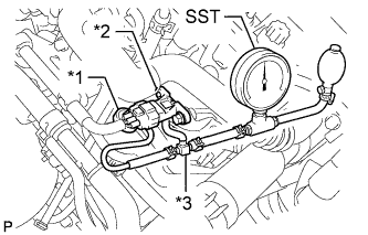 |
Using a 3-way connector, connect SST (turbocharger pressure gauge) to the hose between the diesel turbo pressure sensor and the gas filter leading to the intake air connector.
| *1 | Gas Filter |
| *2 | Diesel Turbo Pressure Sensor |
| *3 | 3-Way Connector |
While depressing the clutch pedal, fully depress the accelerator pedal. Measure the turbocharging pressure at maximum speed (5100 to 5250 rpm).
| 5. CHECK TURBOCHARGER SUB-ASSEMBLY |
Remove the cowl top ventilator louver (Click here).
Remove the No. 1 engine cover.
Remove the No. 1 turbo insulator.
Disconnect the vacuum hose from the actuator.
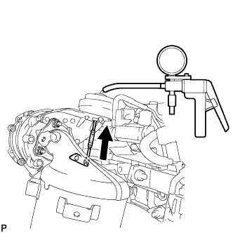 |
Connect a vacuum pump to the actuator.
Check that the rod moves toward the actuator when vacuum is applied to the actuator.
If the rod does not move, replace the turbocharger sub-assembly.
Install the No. 1 turbo insulator.
Install the No. 1 engine cover.
Install the cowl top ventilator louver (Click here).