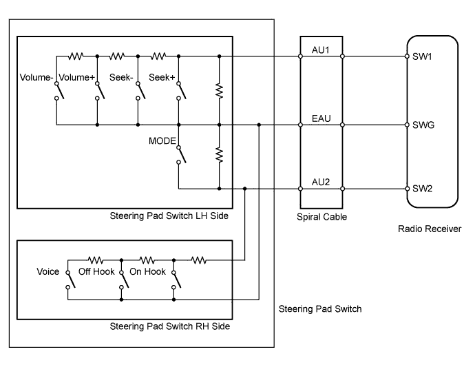
AUDIO AND VISUAL SYSTEM > Steering Pad Switch Circuit |
| 1.INSPECT STEERING PAD SWITCH ASSEMBLY |
Remove the steering pad switch assembly (Click here).
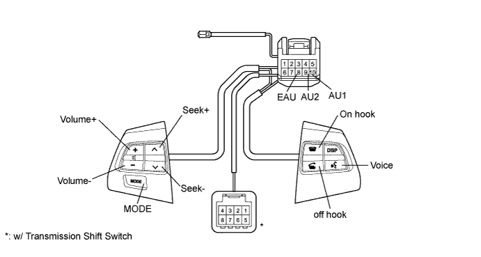
Measure the resistance according to the value(s) in the table below.
| Tester Connection | Switch Condition | Specified Condition |
| 10 (AU1) - 8 (EAU) | No switch is pushed | 95 to 105 kΩ |
| Seek+ switch is pushed | Below 2.5 Ω | |
| Seek- switch is pushed | 312 to 345 Ω | |
| Volume+ switch is pushed | 950 to 1050 Ω | |
| Volume- switch is pushed | 2954 to 3265 Ω | |
| 9 (AU2) - 8 (EAU) | No switch is pushed | 95 to 105 kΩ |
| MODE switch is pushed | Below 2.5 Ω | |
| On hook switch is pushed | 312 to 345 Ω | |
| Off hook switch is pushed | 950 to 1050 Ω | |
| Voice switch is pushed | 2954 to 3265 Ω |
|
| ||||
| OK | |
 |
| 2.INSPECT SPIRAL CABLE SUB-ASSEMBLY |
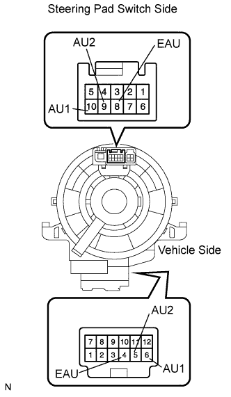 |
Remove the spiral cable (Click here).
Measure the resistance according to the value(s) in the table below.
| Tester Connection | Condition | Specified Condition |
| 4 (EAU) - 8 (EAU) | Spiral cable is turned 2.5 rotations counterclockwise | Below 1 Ω |
| Spiral cable is centered | ||
| Spiral cable is turned 2.5 rotations clockwise | ||
| 6 (AU1) - 10 (AU1) | Spiral cable is turned 2.5 rotations counterclockwise | Below 1 Ω |
| Spiral cable is centered | ||
| Spiral cable is turned 2.5 rotations clockwise | ||
| 5 (AU2) - 9 (AU2) | Spiral cable is turned 2.5 rotations counterclockwise | Below 1 Ω |
| Spiral cable is centered | ||
| Spiral cable is turned 2.5 rotations clockwise |
|
| ||||
| OK | |
|
| 3.CHECK HARNESS AND CONNECTOR (RADIO RECEIVER - SPIRAL CABLE) |
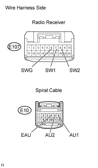 |
Disconnect the E107 radio receiver connector.
Disconnect the E10 spiral cable connector.
Measure the resistance according to the value(s) in the table below.
| Tester Connection | Specified Condition |
| E107-7 (SW1) - E10-6 (AU1) | Below 1 Ω |
| E107-8 (SW2) - E10-5 (AU2) | Below 1 Ω |
| E107-6 (SWG) - E10-4 (EAU) | Below 1 Ω |
| E107-7 (SW1) - Body ground | 10 kΩ or higher |
| E107-8 (SW2) - Body ground | 10 kΩ or higher |
| E107-6 (SWG) - Body ground | 10 kΩ or higher |
|
| ||||
| OK | ||
 | ||
| ||
