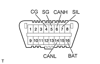
When troubleshooting a vehicle with a diagnosis system, connect the intelligent tester to the DLC3 of the vehicle and read various data output from the steering lock ECU.
The steering lock ECU records DTCs when the computer detects a malfunction in the computer itself or in its circuits.
The diagnosis information of the steering lock ECU is transmitted to the tester via the certification ECU as the steering lock ECU is not connected to the CAN communication system.
The steering lock ECU does not store DTCs regarding past problems.
- HINT:
- When the engine switch is off, the main body ECU to which the intelligent tester is to be connected may not be working.
- Communication with the intelligent tester is impossible if the main body ECU is not working.
As the computer's memory data will be deleted, do not remove the fuses or disconnect the battery terminals until the DTCs are checked and noted.
Malfunctions related to systems other than the steering lock ECU's system may cause DTCs to be output. Note DTCs related to other systems.